OLC
|
|
|
- しおり てらわ
- 4 years ago
- Views:
Transcription
1 OLC
2 Master thesis Molecular Dnamics Studies on Friction Mechanism of OLC Hideaki NISHIMURA Feburar 2013 Department of Mechanical Engineering, Graduate School of Engineering, Kobe Universit, Kobe, Japan
3 OLC OLC Stone-Wales 60n 2 (n=1 6) OLC OLC OLC OLC OLC OLC C 60 OLC 10 2 C 960 C 1500 OLC OLC 10 1 OLC OLC
4 Summar OLC is epected as new solid lubricant because of its spherical structure. For a new insight on the friction properties of OLC thin film, various molecular dnamics (MD) simulations are performed on the compression and friction of isolated fullerene/olc and thin films composed of the arra of fullerenes/olcs. First, we have made spherical fullerenes based on the polhedral rule of 60n 2 (n=1 6) atoms with Stone-Wales defects. OLCs were also made b nesting these fullerenes. Then we performed various compression simulations on isolated fullerene/olc. In the point compression b holding the five-membered ring at the top and bottom of fullerene/olc, the OLCs showed higher strength than the fullerenes because of its multi-laer structure. Detail observation revealed that the internal fullerene in the OLC receives higher force than the isolated fullerene. According to the compression b a flat diamond wall, we also found the following facts; (1) the OLCs show higher stress than the fullerenes at the earl stage of compression, (2) the smaller fullerene/olc shows higher stress than the larger ones, and (3) the OLC shows drastic stress increase when the center C 60 was collapsed. Then we performed various scratch simulations on isolated fullerene/olc b a flat diamond wall changing the indentation depth. The friction coefficient showed the order of 10 2 regardless of the indentation depth or collapse morphologies of the target (fullerene/olc). Here, the target carbons glide without rotation under scratch, ecept the OLCs of half crushed C 960 and C We cannot find out the relationship between the friction coefficient and the sie of fullerenes; however, the large OLC showed lower friction coefficient than the small OLC. Finall, we performed scratch simulations on fullerene/olc thin film. When we introduced the surface roughness of a indenter/substrate, the friction coefficient increased to the order of This magnitude agrees with eperimental result. All the fullerene/olc rotate under the scratch, because the were held b the serrated surface. We found that the fullerene shows much higher friction coefficient than the OLC since the can deform to fit their shape to the surface roughness.
5 Brenner Lennard-Jones OLC i
6 ii
7 1 C [1] 60 (CNT) [2] 1992 Nature Ugarte (Onion-Like Carbon:OLC) [3] ( 1.1) OLC (Transmission Electron Microscope:TEM) nm nm C [nm] [4] [5] Kunetsov OLC [4],[6] Hirata Igarashi OLC 0.1 [7] Jol-Pottu Ohmae OLC [8] [10] [11] [13] C 60 CNT 1
8 1 2 C 60 [14] CNT [15] CNT CNT [16] Hirai, Nishimaki, CNT [17] Deguchi Yamaguchi CNT Stone-Wales [18] CNT CNT [19] Tight Binding [20],[21] OLC TEM OLC C 60 (0.334[nm]) n 60n 2 [22] [23] OLC TEM OLC OLC Saito [24] Terrones 60n 2 Stone-Wales [25] Wang Chang Stone-Wales [26] [27],[28] OLC C 60 C 240 C 540 OLC [29],[30]
, 6. 10 nm Fig.1.1 TEM image of OLC.")
9 1 3 OLC OLC OLC OLC 2, OLC OLC 3 5 OLC ( OLC ), nm Fig.1.1 TEM image of OLC. [3]
10 2 2.1 (molecular dnamics method MD ) m i d 2 r i dt 2 = F i (2.1) m i r i i i F i Φ tot F i = Φ tot r i (2.2) (2.1) Verlet Verlet t + t t t i r i (t ± t) Talor r i (t + t) = r i (t) + t dr i (t) dt r i (t t) = r i (t) t dr i (t) dt + ( t)2 2 + ( t)2 2 v i t i d 2 r i (t) + O ( ( t) 3) dt 2 (2.3) d 2 r i (t) + O ( ( t) 3) dt 2 (2.4) dr i dt = v i (t) (2.5) 4
11 2 5 (2.1) (2.5) (2.3) (2.4) r i (t + t) = r i (t) + tv i (t) + ( t)2 2 r i (t t) = r i (t) tv i (t) + ( t)2 2 F i (t) + O ( ( t) 3) m i (2.6) F i (t) + O ( ( t) 3) m i (2.7) r i (t + t) + r i (t t) = 2r i (t) + ( t) 2 F i (t) m i + O ( ( t) 4) (2.8) r i (t + t) r i (t t) = 2 tv i (t) + O ( ( t) 3) (2.9) t + t t r i (t + t) = 2r i (t) r i (t t) + ( t) 2 F i (t) m i + O ( ( t) 4) (2.10) v i (t) = 1 2 t {r i (t + t) r i (t t)} + O ( ( t) 2) (2.11) t + t 2 t t t (t = 0) t = t r i ( t) (2.6) Brenner Tersoff Brenner [31] 2 sp 2 sp 3
12 2 6 Φ tot = i j(>i) f c (r ij ) [ V R (r ij ) B ij V A (r ij ) ] (2.12). r ij i, j V R (r ij ) B ij V A (r ij ) f c (r ij ). D e V R (r ij ) = S 1 ep [ β 2S (r ij R e ) ] (2.13) V A (r ij ) = S D e 2 S 1 ep β S (r ij R e ) (2.14) 1, r ij < R [ ( )] 1 π (rij R f c (r ij ) = 1 + cos 1 ) R 2 R /2, R 1 < r ij < R 2 (2.15) 1 0, r ij > R 2 Bij i j k 3, B ij = 1 2 (B ij + B ji ) (2.16) B ij, B ji i, j B ij B ji. B ij = [1 + G(θ i )f c (r ik )] δ (2.17) k i,j B ji = [1 + G(θ j )f c (r jk )] δ (2.18) k i,j r ik i, k, r jk j, k. θ i i j i k, θ j j i j k., G(θ i )f c (r ik ) ζ ij, G(θ j )f c (r jk ) ζ ji. G(θ) G(θ) = a 0 [ 1 + c2 0 c 2 0 d 2 0 d (h + cos θ) 2 ] (2.19). (2.12) (2.19) C 2
13 2 7 fcc 2.1 Table 2.1 Potential parameters for Brenner potential. D e [ev] 6.0 R e [nm] β [nm 1 ] 0.21 S 1.22 h 1.0 a c d R 1 [nm] 0.17 R 2 [nm] 0.20 h 1 h 0 h [deg.] Brenner, 1, , [deg.],, j, k.
14 θ = 30 θ = 60 θ = 120 θ = 180 E [ev] r [nm] Fig.2.1 Relationship between potential energ and bond length r[nm] θ[deg] Fig.2.2 Relationship between stable bond length and bending angle.
15 Lennard-Jones Van der Waals Lennard-Jones [32] Φ tot = i j( i) ( ) 12 ( ) 6 4ϵ σ σ (2.20) r ij r ij 1 2 (2.20) 2.2, 2.3 Table 2.2 Potential parameters for Van der Waals. ϵ σ [ev] [nm] E [ev] r [nm] Fig.2.3 Relationship between Van der Waals potential and atomic distance.
16 (2.2) Brenner ij. r i, r j, r k Φ ij = V R (r ij ) B ij + B ji V A (r ij ) (2.21) 2 F i = Φ ij r i, F j = Φ ij r j, F k = Φ ij r k, j > i.. i F i = [ Bij V A(r ij ) V R(r ij ) ] r ij + 1 [ r ij 2 V Bij A(r ij ) r i + B ] ji ri (2.22). r. V R (r ij ), V A (r ij ) r ij D e V R(r ij ) = β 2S S 1 ep [ β 2S (r ij R e ) ] r ij (2.23) r ij 2 V A(r S D e 2 ij ) = β S S 1 ep β S (r ij R e ) r ij (2.24) r ij. f c (r ij ) r ij f c (r ij ) 1 ( ) π π (rij R 1 ) sin : R 2 > r ij > R 1 = 2 R 2 R 1 R 2 R 1 (2.25) r ij 0 : r ij < R 1, R 2 < r ij. B ij, B ji r i. B ij r i ζ ij r i = = δ(1 + ζ ij ) δ 1 ζ ij (2.26) r i ( i f c(r ik )G(θ i ) r ik + f c (r ik )G (θ i ) cos θ ) i (2.27) r ik r i k i,j G (θ) G(θ) cos θ. G (θ) = G(θ) [ cos θ = a 2c 2 ] 0(1 + cos θ) 0 [d (1 + cos θ) 2 ] 2 (2.28)
17 2 11 cos θ. j, i, k B ji. cos θ i = r ij r ik (2.29) r ij r ik ( cos θ i 1 = cos θ ) ( i rij 1 + cos θ ) i rik (2.30) r i r ik r ij r ij r ij r ik r ik B ji = (1 + ζ ji ) δ B ji r i = δ (1 + ζ ji ) δ 1 ζ ji r i (2.31) j ζ ji = f c (r jk )G (θ j ) cos θ j (2.32) r i r i k i,j cos θ j = r ji r jk r ji r jk (2.33) cos θ j = 1 r jk + cos θ j r ji r i r ji r jk r ji r ji (2.34) F i = [ Bij V A(r ij ) V R(r ij ) ] r ij r ij V A(r ij ) ( δ (1 + ζ ij ) δ 1) i V A(r ij ) ( δ (1 + ζ ji ) j k i,j j δ 1) k i,j f c (r ik )G (θ i ) ( ) 1 r ik cos θ i r ij ) cos θ i r ik f c(r ik )G(θ i ) + f c (r ik )G (θ i ) ( 1 f c (r jk )G (θ j ) cos θ j r ji f c (r jk )G (θ j ) 1 r ji F j = [ Bij V A(r ij ) V R(r ij ) ] ( r ) ij + 1 [ r ij 2 V Bij A(r ij ) r i r ji r ji rjk r jk + B ] ji r i r ij (2.35) r ij r ij r ik r ik. B ij ζ ij ζ ij r i = i k i,j ( f c (r ik )G (θ i ) cos θ i r j ) (2.36) ζ ji r j = j k i,j cos θ i = 1 r ik + cos θ i r j r ij r ik r ij ( f c(r jk )G(θ j ) r jk + f c (r jk )G (θ j ) cos θ j r jk r j r ij r ij (2.37) ) (2.38)
18 2 12 ( cos θ j 1 = cos θ ) ( j rji 1 + cos θ ) j rjk (2.39) r j r jk r ji r ji r ji r jk r jk F j = [ Bij V A(r ij ) V R(r ij ) ] ( r ) ij r ij V A(r ij ) ( δ (1 + ζ ij ) δ 1) i V A(r ij ) ( δ (1 + ζ ji ) k k i,j j δ 1) k i,j F k = 1 2 V A(r ij ) f c (r ik )G (θ i ) cos θ i r ij f c (r ik )G (θ i ) 1 r ij r ij ij r ik r ik f c (r jk )G (θ j ) ( 1 r jk cos θ ) j r ji f c(r jk )G(θ j ) + f c (r jk )G (θ j ) ( 1 r ji cos θ ) j r jk [ Bij r k + B ] ji r k (2.40) r ji r ji rjk r jk. B ij, B ji ζ ij, ζ ji ζ ij r k = ζ ji r k = i k i,j j ( k i,j ( ( f c(r ik )G(θ i ) r ) ik + f c (r ik )G (θ i ) cos θ ) i r ik r k ( f c(r jk )G(θ j ) r ) jk + f c (r jk )G (θ j ) cos θ ) j r jk r k (2.41) (2.42). F k = 1 2 V A(r ij ) ( δ (1 + ζ ij ) δ 1) i V A(r ij ) ( δ (1 + ζ ji ) k i,j j δ 1) k i,j Van der Waals f c (r ik )G (θ i ) 1 r ik f c(r ik )G(θ i ) + f c (r ik )G (θ i ) ( cos θ i r ik ) f c (r jk )G (θ j ) 1 r jk f c(r jk )G(θ j ) + f c (r jk )G (θ j ) cos θ j r jk r ij r ij r ik ik r ji r ji rjk r jk F i = Φ(r ij) r ij = 4ϵ 12 ( ) 12 σ + 6 ( ) 6 σ r ij (2.43) r j( i) ij r ij r ij r ij r ij F j = F i (2.44) i j k r ij, r ik i, j i, k θ i r ij, r ik
19 N 1step N (N 1) N ( r c ) 2.4 r c r fc r c N (r c N 1) r fc r c (N (N 1) ) rfc rc Fig.2.4 Schematic of bookkeeping method.
20 b b N b 0 b Fig.2.5 Schematic of domain decomposition method.
21 (2.45) 1 2 mα v α i v α i = 3 2 k BT (2.45) m α : α v α i k B : T α : Boltmann = [J/K] T 0 α v α i 0 v α i 0 (2.46) ( ) 0.5 vi α 3kB T 0 0 = (2.46) T α (2.47) v α i = m α ( ) 0.5 3kB T (2.47) m α (2.46) (2.47) vi α 0 vi α = ( T0 T ) 0.5 (2.48) T T 0 (2.48) Verlet r α i (t+ t) 2.49 T 0 /T r α i (t + t) r α i (t + t) = r α i (t + t) r α i (t) = r α i (t) r α i (t t) + ( t) 2 F α i (t) m α (2.49) [33]
22 [23] Euler 12 (Isolated Pentagon Rule) C 60 [23] 60n 2 [34] (Stone-Wales ) C 240 C 60 C C C 960 (a) Before inserting (b) After inserting Fig.2.6 Snapshots of Stone-Wales defect.
 After inserting Fig.2.")
 Before inserting")

23 2 17 (a) Before inserting (b) After inserting Fig.2.7 Snapshots of epanded C 540. (a) Before inserting (b) After inserting Fig.2.8 Snapshots of epanded C 960.
24 n 2 n=1 6 ( ) 20000[fs], 0.145[nm]. Mawell Boltmann 10[K] 1.0[fs] n r OLC n r 3.1 C nm ( ) (0.336nm) 3.1 C
25 3 19 Table 3.1 Fullerene parameter n, radius and radius difference after relaation. fullerene n radius [nm] radius difference [nm] C C C C C C (a) top view (b) side view ( 1 ) (c) side view ( 2 ) Fig.3.1 Snapshots of C 1500 after relaation.
26 n= [/fs] Mawell Boltmann 10[K] 1.0[fs] 3.2 C (ii) 3.2(i) 3.2(i) ε < 0.05 (a)ε = (b)ε = 0.03 (b)ε = 0.03 (c)ε = (ii) (b) (b) (c) 3.2(i) 0.05 < ε < 0.22 (c)ε = 0.05 (d)ε = (ii) (e) 3.3 C (i) (a) (b) (b) (c) 3.3(ii) C 540 (b) 3.3(i) < ε < 0.3 (c) (d) C 540 (d)
27 (ii) (e) 3.4 C (i) (a) (c) 3.4(ii) (d) (f) C C (i) (a) (c) (d) ( 3.5(ii) (e) ) 3.6 C 540 ε = 0.17 σ = 2.21[GPa] C 960 ε = 0.23 σ = 1.14[GPa] C 1500 ε = σ = 1.12[GPa] C 2160 ε = σ = 0.52[GPa] bond 3.7 ( 2.7 ) 3.7 C 540 C 1500 C 960 C 2160 C 540 C 1500 C 960 C 2160
28 3 22 Compressive stress, -σ, GPa (a) (b) (c) (d) (e) C 540 (f) Compressive strain, ε (i) Stress - strain curve of C 540 under compression. close-up bottom view (a) ε =0.005 (b) ε =0.03 (c) ε=0.05 close-up bottom view (d) ε =0.17 (e) ε =0.19 (f) ε=0.215 (ii) Snapshots of C 540 under compression. Fig.3.2 Compression of C 540 b holding the five-membered ring at the top and bottom.
29 3 23 C 960 Compressive stress, -σ, GPa (a) (b) (c) (d) (e) (f) Compressive strain, ε (i) Stress - strain curve of C 960 under compression. (a) ε =0.045 (b) ε =0.055 close-up top view (c) ε=0.095 (d) ε =0.23 (e) ε =0.245 close-up top view (f) ε=0.27 (ii) Snapshots of C 960 under compression. Fig.3.3 Compression of C 960 b holding the five-membered ring at the top and bottom.
30 3 24 C 1500 Compressive stress, -σ, GPa (b) (a) (c) (d) (e) Compressive strain, ε (f) (i) Stress - strain curve of C 1500 under compression. (a) ε =0.015 (b) ε =0.025 close-up bottom view (c) ε =0.06 (d) ε =0.175 (e) ε =0.18 close-up bottom view (f) ε=0.295 (ii) Snapshots of C 1500 under compression. Fig.3.4 Compression of C 1500 b holding the five-membered ring at the top and bottom.
31 3 25 C 2160 Compressive stress, -σ, GPa (a) (d) (e) (c) (f) (b) Compressive strain, ε (i) Stress - strain curve of C 2160 under compression. (a) ε =0 (b) ε =0.01 close-up top view (c) ε =0.125 (d) ε =0.245 (e) ε =0.255 close-up top view (f) ε=0.3 (ii) Snapshots of C 2160 under compression. Fig.3.5 Compression of C 2160 b holding the five-membered ring at the top and bottom.
32 3 26 Compressive stress, -σ, GPa C 540 C 960 C 1500 C Compressive strain, ε Fig.3.6 Stress - strain curves of fullerenes under compression. (a) C540 (b) C960 (c) C1500 (d) C2160 Fig.3.7 Top view of fullerenes after stress peak.
![3 27 3.2.2 n=3 6 0.44[nm] 20000[fs] 3.8 1[nm] D 3/4D 0.7[nm] 1.0 10 4 [nm/fs]. 7.](/docs-images/109/186975928/images/33-0.jpg "1[nm] Van der Waals Mawell Boltmann 10[K] 1.0[fs] 1nm 7.1nm Fig.3.")
33 n= [nm] 20000[fs] 3.8 1[nm] D 3/4D 0.7[nm] [nm/fs]. 7.1[nm] Van der Waals Mawell Boltmann 10[K] 1.0[fs] 1nm 7.1nm Fig.3.8 Schematic of wall compression (C 1500 ).
34 C (ii) 3.9(i) 3.9(i) (i) (a) 0.6[nm] Van der Waals Van der Waals 0.37[nm] 0.6[nm] (1[nm]-0.37[nm]) (a) (d) 1.15[nm] 3.9(ii) (d) (e) 3.2(ii) (f) 1.7[nm] 3.9(ii) (f) 3.10 C (i) (a) (b) (c) (c) (e) (a) (b) 3.10(ii) 3.3(ii) (b) (e) (f) (h) (e) C 540 (f) 3.10(ii) (f) (g) (h) 3.11 C 1500 C (ii) (f)
35 C 2160 (h) 3.12(ii) (c) (d) 3.5(ii) 3.12(ii) (f) (g) (h) 3.12(ii) (h) (i) (h) Van der Waals 3.13 C C [nm] C [nm] C [nm] C [nm] (C (ii) (f) C (ii) (h) C (ii) (f) C (ii) (i)) 3.14 C 540 C 1500 C 2160
36 3 30 C 540 Compressive stress, -σ, GPa 4 (d) (f) 2 (e) (b) (c) 0 (a) Displacement of upper wall, nm (i) Stress - displacement curve of C 540 under compression. (a) 0.6nm indentation (b) 0.85nm indentation (c) 0.9nm indentation (d) 1.15nm indentation (e) 1.4nm indentation (f) 1.85nm indentation (ii) Snapshots of C 540 under compression. Fig.3.9 Compression of C 540 b diamond wall.
37 3 31 C 960 Compressive stress, -σ, GPa (a) (c) (b) (f) (g) (e) (d) (h) Displacement of upper wall, nm (i) Stress - displacement curve of C 960 under compression. (a) 0.85nm indentation (b) 0.95nm indentation (c) 1.3nm indentation (d) 1.8nm indentation (e) 2.0nm indentation (f) 2.3nm indentation (g) 2.4nm indentation (h) 2.5nm indentation (ii) Snapshots of C 960 under compression. Fig.3.10 Compression of C 960 b diamond wall.
38 3 32 C 1500 Compressive stress, -σ, GPa (a) (c) (b) (d) (e) (f) Displacement of upper wall, nm (i) Stress - displacement curve of C 1500 under compression. (a) 0.8nm indentation (b) 0.85nm indentation (c) 1.4nm indentation (d) 1.7nm indentation (e) 2.2nm indentation (f) 2.9nm indentation (ii) Snapshots of C 1500 under compression. Fig.3.11 Compression of C 1500 b diamond wall.
39 3 33 C 2160 Compressive stress, -σ, GPa 4 2 (f) (c) (i) (a) (g) (h) 0 (b) (d) (e) Displacement of upper wall, nm (i) Stress - displacement curve of C 2160 under compression. (a) 0.8nm indentation (b) 0.85nm indentation (c) 1.9nm indentation (d) 2.2nm indentation (e) 2.6nm indentation (f) 2.9nm indentation (g) 3.0nm indentation (h) 3.3nm indentation (i) 3.7nm indentation (ii) Snapshots of C 2160 under compression. Fig.3.12 Compression of C 2160 b diamond wall.
40 3 34 Compressive stress, -σ, GPa C 540 C 960 C 1500 C Displacement of upper wall, nm Fig.3.13 Stress - displacement curves of fullerenes under compression. (a) C540 (b) C960 (c) C1500 (d) C2160 Fig.3.14 Snapshots of fullerenes at the point just before the drastic stress increase.
![3 35 3.3 3.3.1 n=3 6 3.15 1[nm] 4 C 540 10.7[nm] C 960 12.8[nm] C 1500 14.9[nm] C 2160 17.1[nm] 1nm+0.1D 1nm+0.](/docs-images/109/186975928/images/41-0.jpg "3D 1nm+0.5D 1nm+0.7D 4 (D ) 3D 1.0 10 4 [nm/fs]. 1nm 14.9nm Fig.3.15 Schematic of scratch simulation (C 1500 ).")
41 n= [nm] 4 C [nm] C [nm] C [nm] C [nm] 1nm+0.1D 1nm+0.3D 1nm+0.5D 1nm+0.7D 4 (D ) 3D [nm/fs]. 1nm 14.9nm Fig.3.15 Schematic of scratch simulation (C 1500 ).
42 C nm+0.1D 1nm+0.3D ±0.1 1nm+0.5D ±0.05 1nm+0.7D ±0.02 1nm+0.1D (a) C 540 ( ) (b) (d) ( 3.2) 10 2 C 960 C 2160 C 540 C C nm+0.3D C 540 C C 1500
43 3 37 1nm+0.5D C nm+0.7D Van der Waals ( 3.5 ) nm+0.7D
44 3 38 average average Friction coefficient, µ Friction coefficient, µ Displacement of upper wall, nm Displacement of upper wall, nm (a) 1nm+0.1D indentation (b) 1nm+0.3D indentation average average Friction coefficient, µ Friction coefficient, µ Displacement of upper wall, nm Displacement of upper wall, nm (c) 1nm+0.5D indentation (d) 1nm+0.7D indentation Fig.3.16 Friction coefficient - displacement curves of C 1500 under scratch.
 C540 (b) C960 (c) C1500 (d) C2160 Fig.3.17 Snapshots of fullerenes after indentation (1nm+0.1D indentation). 14.9nm (a) 0nm scratch (b) D (3.61nm) scratch (c) 2D (7.")
45 3 39 Table 3.2 Friction coefficient of fullerenes (1nm+0.1D indentation). fullerene C 540 C 960 C 1500 C 2160 friction coefficient (a) C540 (b) C960 (c) C1500 (d) C2160 Fig.3.17 Snapshots of fullerenes after indentation (1nm+0.1D indentation). 14.9nm (a) 0nm scratch (b) D (3.61nm) scratch (c) 2D (7.22nm) scratch (d) 3D (10.83nm) scratch Fig.3.18 Snapshots of C 1500 under scratch (1nm+0.1D indentation).
 C540 (b) C960 (c) C1500 (d) C2160 Fig.3.19 Snapshots of fullerenes after indentation (1nm+0.3D indentation). 14.9nm (a) 0nm scratch (b) D (3.61nm) scratch (c) 2D (7.")
46 3 40 Table 3.3 Friction coefficient of fullerenes (1nm+0.3D indentation). fullerene C 540 C 960 C 1500 C 2160 friction coefficient (a) C540 (b) C960 (c) C1500 (d) C2160 Fig.3.19 Snapshots of fullerenes after indentation (1nm+0.3D indentation). 14.9nm (a) 0nm scratch (b) D (3.61nm) scratch (c) 2D (7.22nm) scratch (d) 3D (10.83nm) scratch Fig.3.20 Snapshots of C 1500 under scratch (1nm+0.3D indentation).
47 3 41 Table 3.4 Friction coefficient of fullerenes (1nm+0.5D indentation). fullerene C 540 C 960 C 1500 C 2160 friction coefficient (a) C540 (b) C960 (c) C1500 (d) C2160 Fig.3.21 Snapshots of fullerenes after indentation (1nm+0.5D indentation). 14.9nm (a) 0nm scratch (b) D (3.61nm) scratch (c) 2D (7.22nm) scratch (d) 3D (10.83nm) scratch Fig.3.22 Snapshots of C 1500 under scratch (1nm+0.5D indentation).
48 3 42 Table 3.5 Friction coefficient of fullerenes (1nm+0.7D indentation). fullerene C 540 C 960 C 1500 C 2160 friction coefficient (a) C540 (b) C960 (c) C1500 (d) C2160 Fig.3.23 Snapshots of fullerenes after indentation (1nm+0.7D indentation). 14.9nm (a) 0nm scratch (b) D (3.61nm) scratch (c) 2D (7.22nm) scratch (d) 3D (10.83nm) scratch Fig.3.24 Snapshots of C 1500 under scratch (1nm+0.7D indentation).
49 4 OLC OLC 30000[fs] OLC C 1500 OLC C 1500 C 540 C 960 C 1500 C C OLC 43
50 4 OLC (a) top view (b) side view ( 1 ) (c) side view ( 2 ) Fig.4.1 Snapshots of C 1500 after relaation.
51 4 OLC OLC [/fs] 4.2 C (i) ε < 0.05 (a)ε = 0.01 (b)ε = 0.02 (c)ε = (ii) (b) 4.2(i) (c)ε = 0.05 (d)ε = (ii) (e) C 540 ( 3.7(a) ) C C (i) 4.3(ii) (a) C 540 (b) (e) (b) C 540 (e) C 960 C (a) C (b) 4.4 C (i) ε < 0.05
52 4 OLC (ii) (b) C 540 (c) (e) 4.4(ii) (c) C 540 (d) C 1500 (e) C C (ii) (b) C 540 (c) C 1500 (d) C 960 (e) C OLC OLC OLC 4.5 C 2160 C 540 C 1500 C 960 C C 960 C 1500 C C 540 ( ) OLC
53 4 OLC 540 Compressive stress, -σ, GPa (a) (d) (e)(f) (c) (b) Compressive strain, ε (i) Stress - strain curve of C 540 under compression. (a) ε =0.01 (b) ε =0.02 (c) ε=0.05 (d) ε =0.215 (e) ε =0.225 (f) ε=0.245 (ii) Snapshots of C 540 under compression. Fig.4.2 Compression of C 540 b holding the five-membered ring at the top and bottom.
 ε =0.255 (d) ε =0.265 (e) ε=0.275 (ii) Snapshots of C 960 under compression. Fig.4.3 Compression of C 960 b holding the five-membered ring at the top and bottom.")
54 4 OLC 960 Compressive stress, -σ, GPa (a) (c) (d) (b) (e) Compressive strain, ε (i) Stress - strain curve of C 960 under compression. (a) ε =0.065 (b) ε =0.245 close-up C540 (c) ε =0.255 (d) ε =0.265 (e) ε=0.275 (ii) Snapshots of C 960 under compression. Fig.4.3 Compression of C 960 b holding the five-membered ring at the top and bottom.
55 4 OLC 1500 Compressive stress, -σ, GPa (a) (c) (e) (d) (b) Compressive strain, ε (i) Stress - strain curve of C 1500 under compression. (a) ε =0.025 (b) ε =0.04 (c) ε=0.2 close-up C540 (d) ε =0.22 (e) ε =0.245 close-up C960 (ii) Snapshots of C 1500 under compression. Fig.4.4 Compression of C 1500 b holding the five-membered ring at the top and bottom.
56 4 OLC 2160 Compressive stress, -σ, GPa (a) (b)(c) (d) (e) Compressive strain, ε (i) Stress - strain curve of C 2160 under compression. (a) ε =0.06 (b) ε =0.16 close-up C540 (c) ε=0.185 close-up C1500 (d) ε =0.23 close-up C960 (e) ε =0.26 (ii) Snapshots of C 2160 under compression. Fig.4.5 Compression of C 2160 b holding the five-membered ring at the top and bottom.
57 4 OLC 51 Compressive stress, -σ, GPa Compressive strain, ε Fig.4.6 Stress - strain curves of OLCs under compression. Compressive stress, -σ, GPa C 540 C 960 C 1500 C Compressive strain, ε Fig.4.7 Stress - strain curves of fullerenes under compression.
58 4 OLC OLC 7.1[nm] 7.1[nm] 0.7[nm] [nm/fs]. 4.8 C (i) (i) Van der Waals (a) 0.7[nm] (c) 1.6[nm] (e) 1.9[nm] 4.8(ii) ( 4.2(ii) ) (c) (e) (c) (d) C 540 (e) C OLC 1.0[nm] OLC C 540 Van der Waals 0.7[nm] C (ii) (b) C 1500 OLC C (ii) OLC
59 4 OLC 53 C 1500 C OLC ( 0.9[nm] ) OLC
60 4 OLC 540 Compressive stress, -σ, GPa 10 (c) (e) (d) 5 (b) 0 (a) Displacement of upper wall, nm (i) Stress - displacement curve of C 540 under compression. (a) 0.7nm indentation (b) 0.85nm indentation (c) 1.6nm indentation (d) 1.7nm indentation (e) 1.9nm indentation close-up C60 (ii) Snapshots of C 540 under compression. Fig.4.8 Compression of C 540 b diamond wall.
61 4 OLC 55 Compressive stress, -σ, GPa Displacement of upper wall, Fig.4.9 Stress - displacement curves of OLCs under compression. Compressive stress, -σ, GPa C 540 C 960 C 1500 C Displacement of upper wall, nm Fig.4.10 Stress - displacement curves of fullerenes under compression.
62 4 OLC OLC OLC 4 C [nm] C [nm] C [nm] C [nm] 1nm+0.1D 1nm+0.3D 1nm+0.5D 1nm+0.7D nm+0.1D C OLC (a) 5 1 OLC OLC 4.12 OLC C OLC C nm+0.3D 4.14 OLC nm+0.1D
63 4 OLC 57 ± OLC 1nm+0.1D 4.16 C nm+0.5D C nm+0.3D (b) (c) (d) 3.5[nm] 4.18 OLC C 60 OLC ( 4.3) 1nm+0.1D 1nm+0.3D C OLC 4.19 (b) (d) 4.17 (a) (b) C 60 C 240 (b) (c) (c) (d) 4.17 (c) (e) (f) nm+0.5D C 960 C 540 C 2160 C 960 C nm+0.7D
64 4 OLC C OLC 1nm+0.5D OLC 1nm+0.5D 4.21 OLC C nm+0.5D bond
. OLC R c [nm] friction coefficient C 540 0.78 1.49 10 2 C 960 1.05 0.54 10 2 C 1500 1.25 0.47 10 2 C 2160 1.47 0.")
65 4 OLC 59 average Friction coefficient, µ Displacement of upper wall, nm Fig.4.11 Friction coefficient - displacement curve of C 1500 under scratch (1nm+0.1D indentation). Table 4.1 Radius of contact area and friction coefficient of OLCs (1nm+0.1D indentation). OLC R c [nm] friction coefficient C C C C Fig.4.12 Snapshots of OLCs after indentation (1nm+0.1D indentation). 14.9nm (a) 0nm scratch (b) D (3.61nm) scratch (c) 2D (7.22nm) scratch (d) 3D (10.83nm) scratch Fig.4.13 Snapshots of C 1500 under scratch (1nm+0.1D indentation).
66 4 OLC 60 average Friction coefficient, µ Displacement of upper wall, nm Fig.4.14 Friction coefficient - displacement curve of C 1500 under scratch (1nm+0.3D indentation). Table 4.2 Radius of contact area and friction coefficient of OLCs (1nm+0.3D indentation). OLC R c [nm] friction coefficient C C C C Fig.4.15 Snapshots of OLCs after indentation (1nm+0.3D indentation). 14.9nm (a) 0nm scratch (b) D (3.61nm) scratch (c) 2D (7.22nm) scratch (d) 3D (10.83nm) scratch Fig.4.16 Snapshots of C 1500 under scratch (1nm+0.3D indentation).
. Table 4.3 Radius of contact area and friction coefficient of OLCs (1nm+0.5D indentation). OLC R c [nm] friction coefficient C 540 1.17 1.66 10 2 C 960 1.60 1.45 10 2 C 1500 1.92 1.")
67 4 OLC 61 average Friction coefficient, µ (d) 0.02 (b) (c) Displacement of upper wall, nm Fig.4.17 Friction coefficient - displacement curve of C 1500 under scratch (1nm+0.5D indentation). Table 4.3 Radius of contact area and friction coefficient of OLCs (1nm+0.5D indentation). OLC R c [nm] friction coefficient C C C C Fig.4.18 Snapshots of OLCs after indentation (1nm+0.5D indentation). 14.9nm (a) 0nm scratch (b) 2.8nm scratch (c) 3.5nm scratch surface closeup (d) 5.0nm scratch (e) 7.0nm scratch (f) 3D (10.83nm) scratch Fig.4.19 Snapshots of C 1500 under scratch (1nm+0.5D indentation).
68 4 OLC 62 average Friction coefficient, µ Displacement of upper wall, nm Fig.4.20 Friction coefficient - displacement curve of C 1500 under scratch (1nm+0.7D indentation). Table 4.4 Radius of contact area and friction coefficient of OLCs (1nm+0.7D indentation). OLC R c [nm] friction coefficient C C C C Fig.4.21 Snapshots of OLCs after indentation (1nm+0.7D indentation). 14.9nm (a) 0nm scratch (b) D (3.61nm) scratch (c) 2D (7.22nm) scratch (d) 3D (10.83nm) scratch Fig.4.22 Snapshots of C 1500 under scratch (1nm+0.7D indentation).
69 OLC C 540 C 2160 OLC C 540 C small serrate (S) large serrate (L) (C 540 C [nm] C 2160 C [nm] ) 30000[fs] 1000[nN] 7.5[nm] [nm/fs]. OLC ( [nm 2 ])

 Large serrate indenter 1.24nm 2.49nm Fig.5.1 Dimensions of diamond wall indenter.")
70 5 64 Table 5.1 Diameter, number of atoms and coverage rate in simulation models. model name diameter [nm] No. of atoms coverage rate [%] C C C C nm 14.9nm (a) Small serrate indenter 1.06nm 0.55nm 1.06nm 14.9nm 14.9nm 0.55nm (b) Large serrate indenter 1.24nm 2.49nm Fig.5.1 Dimensions of diamond wall indenter.
")

")

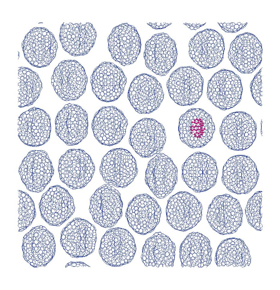
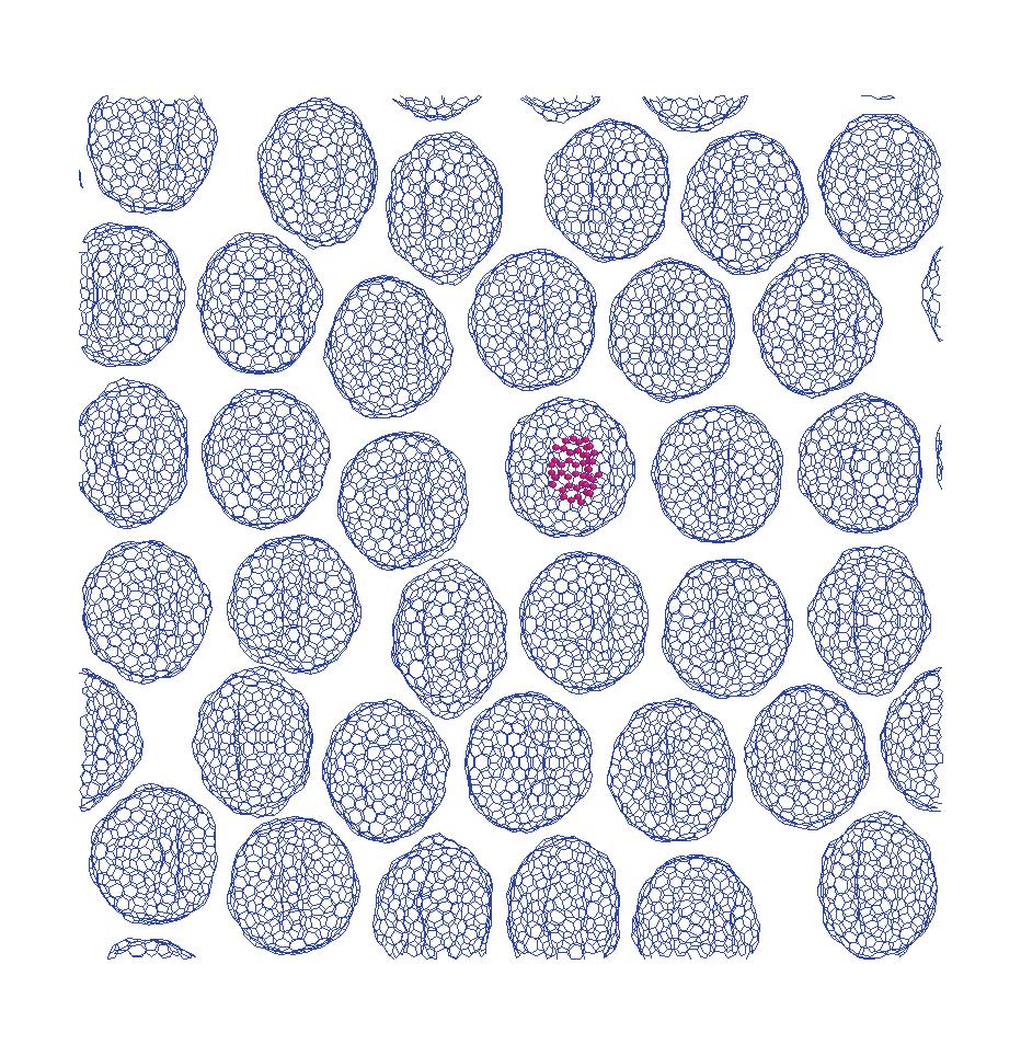
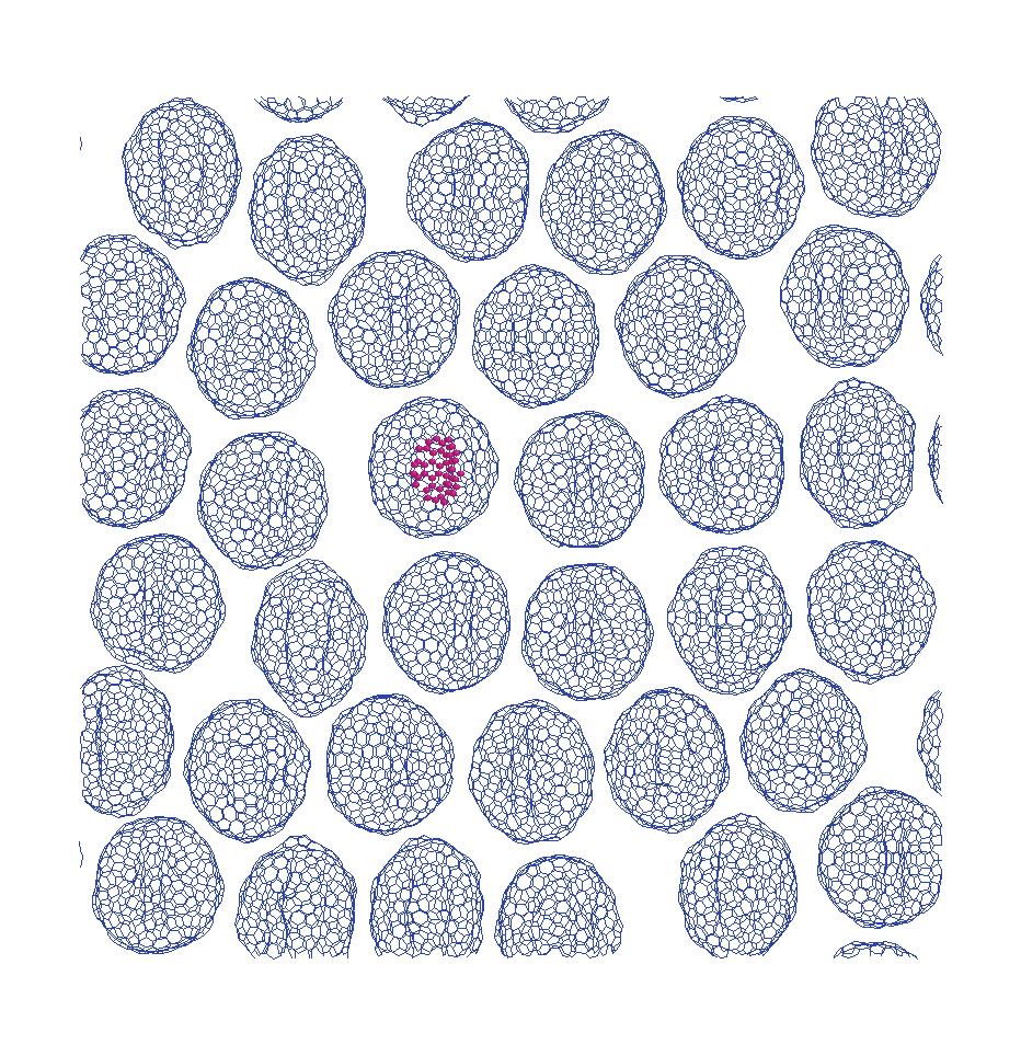
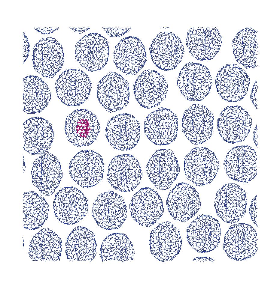
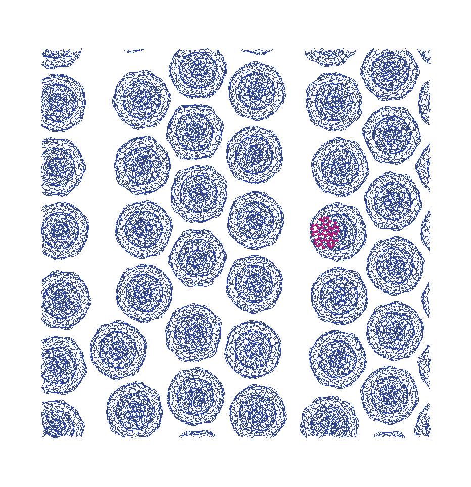
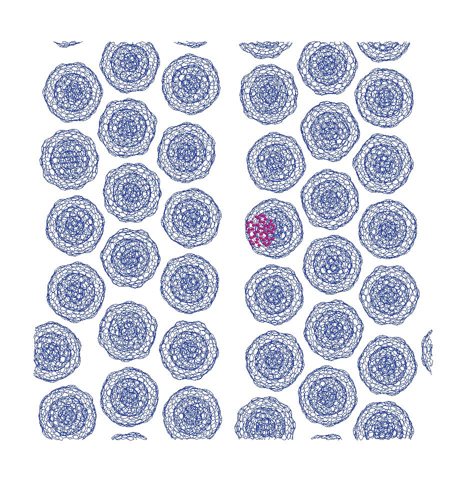
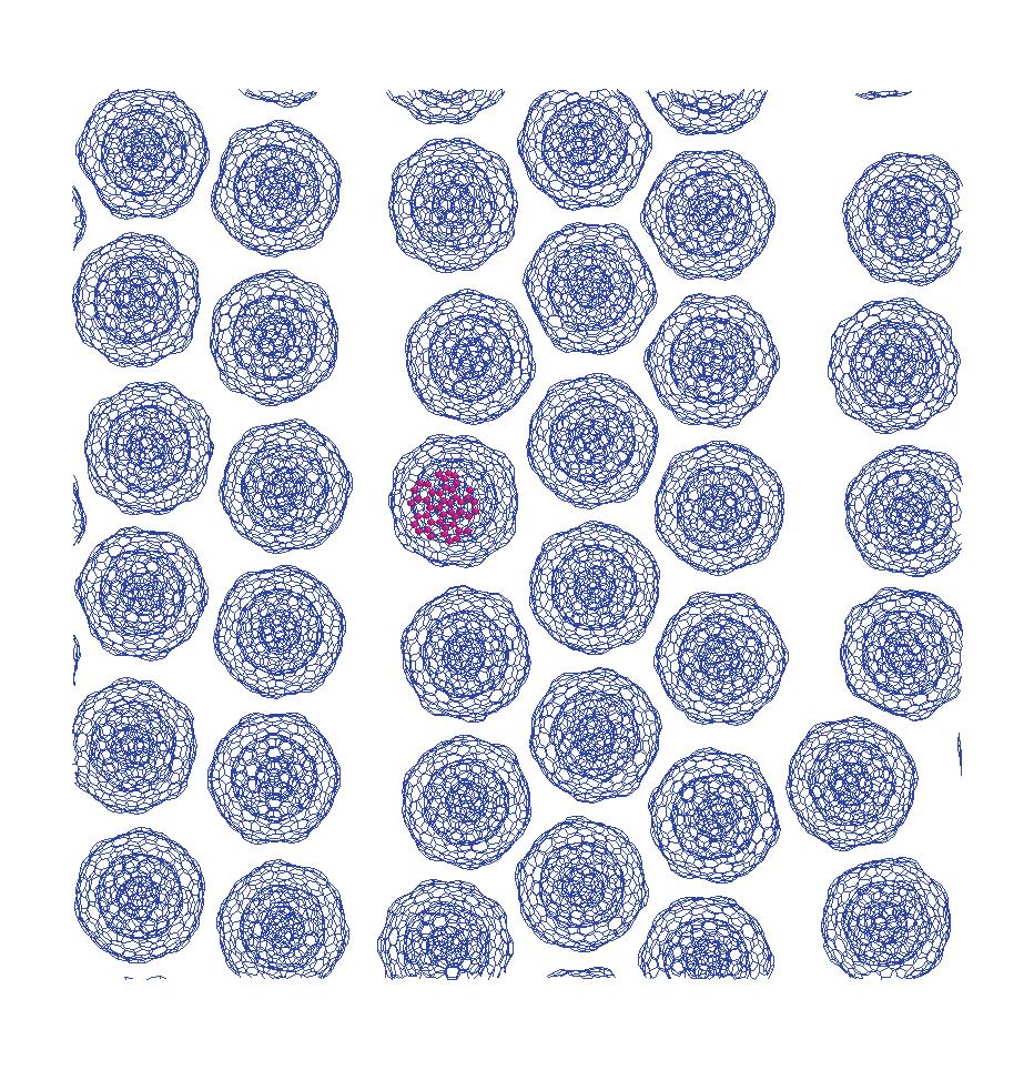
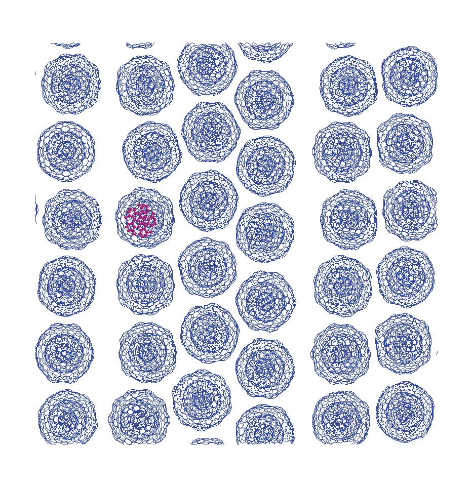
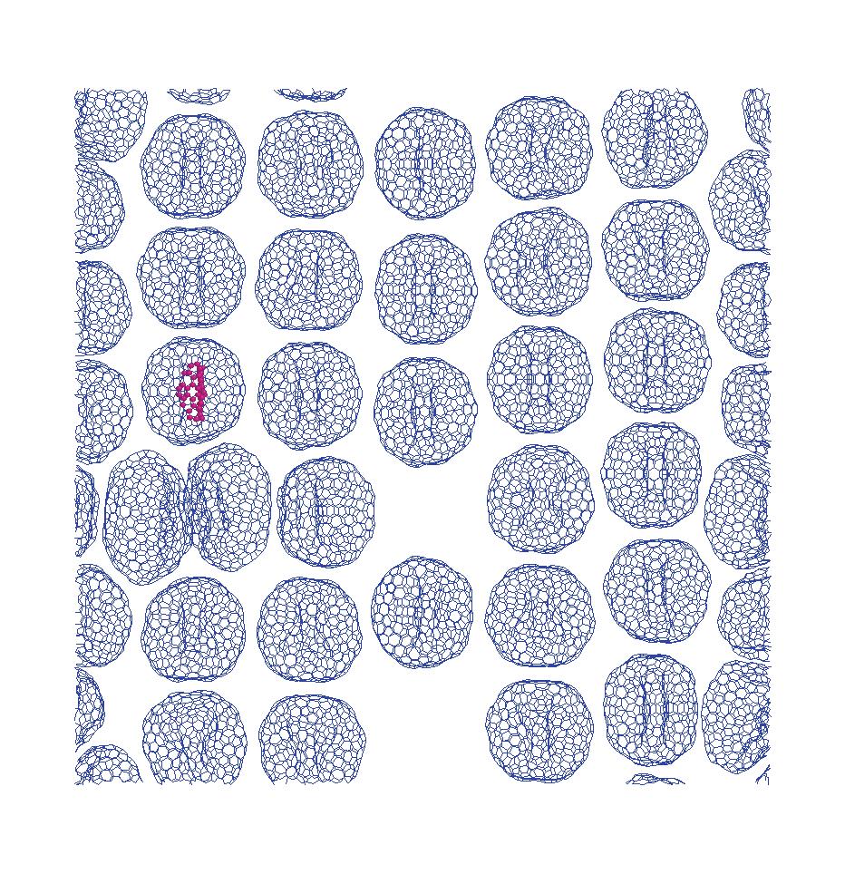
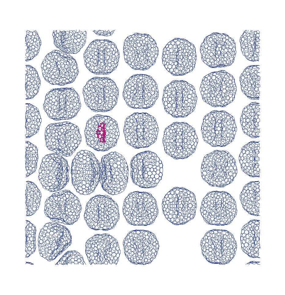
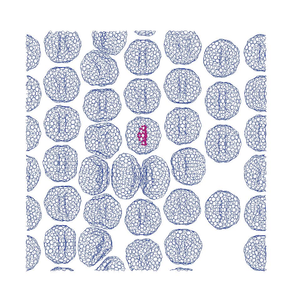
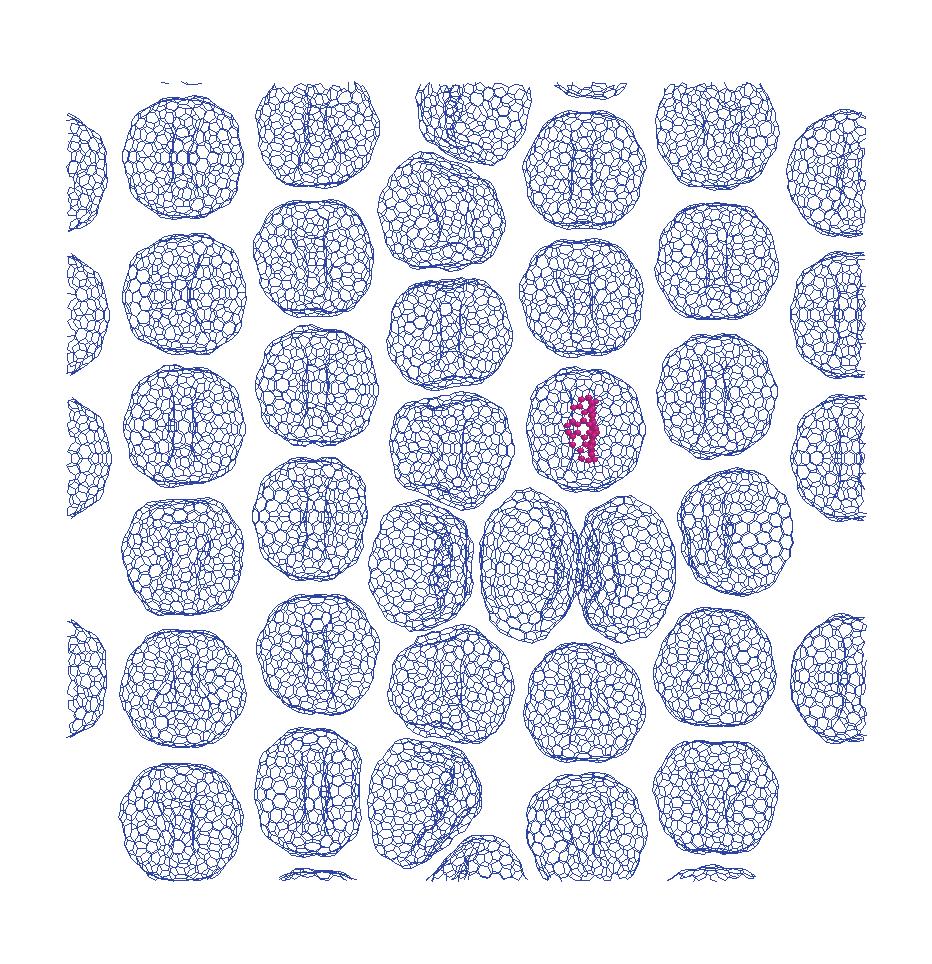
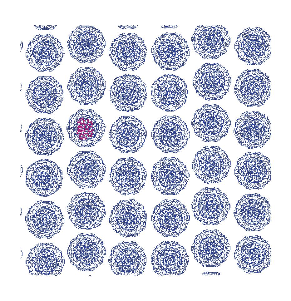
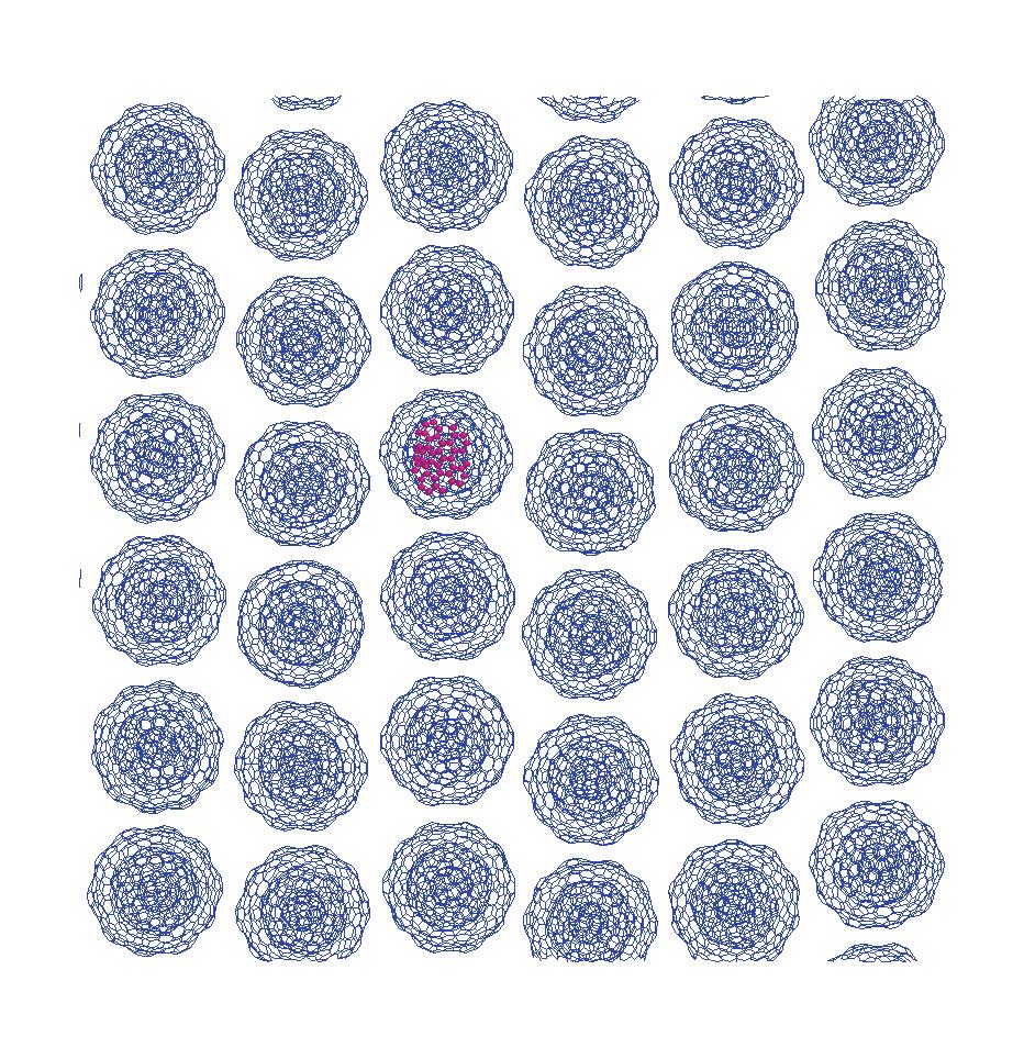
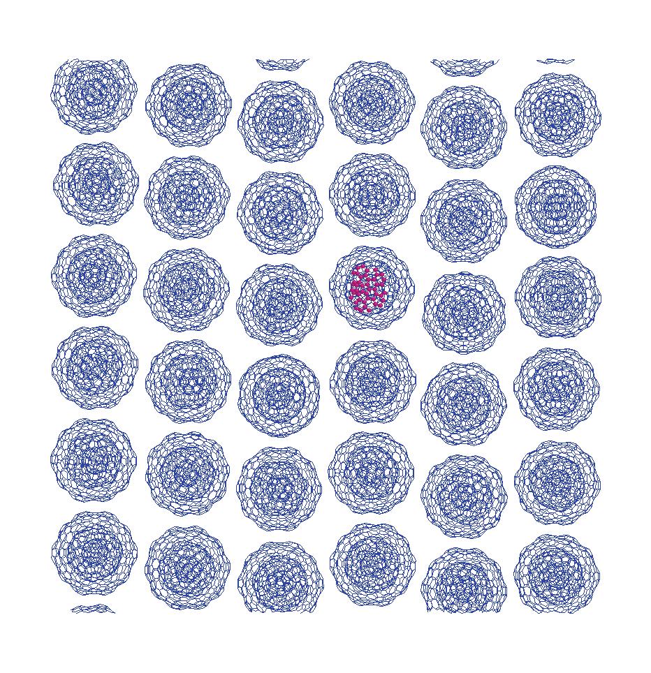
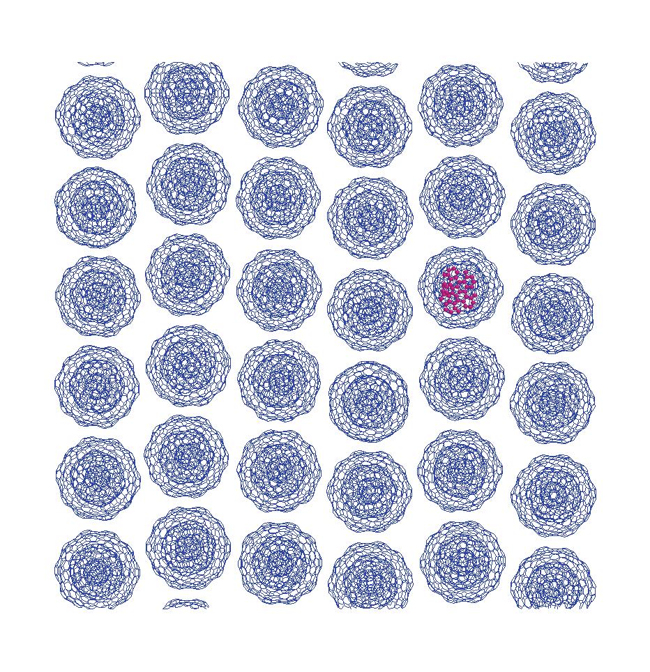
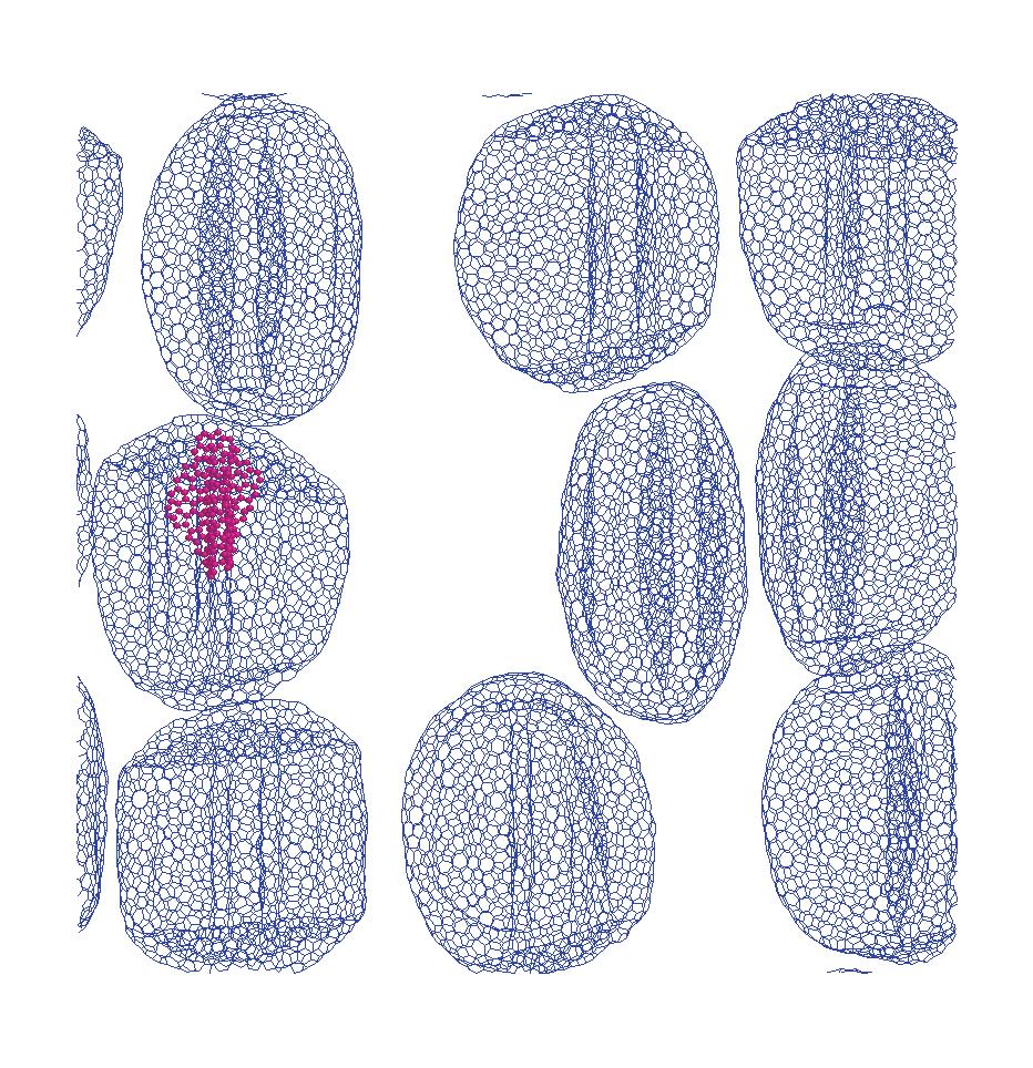
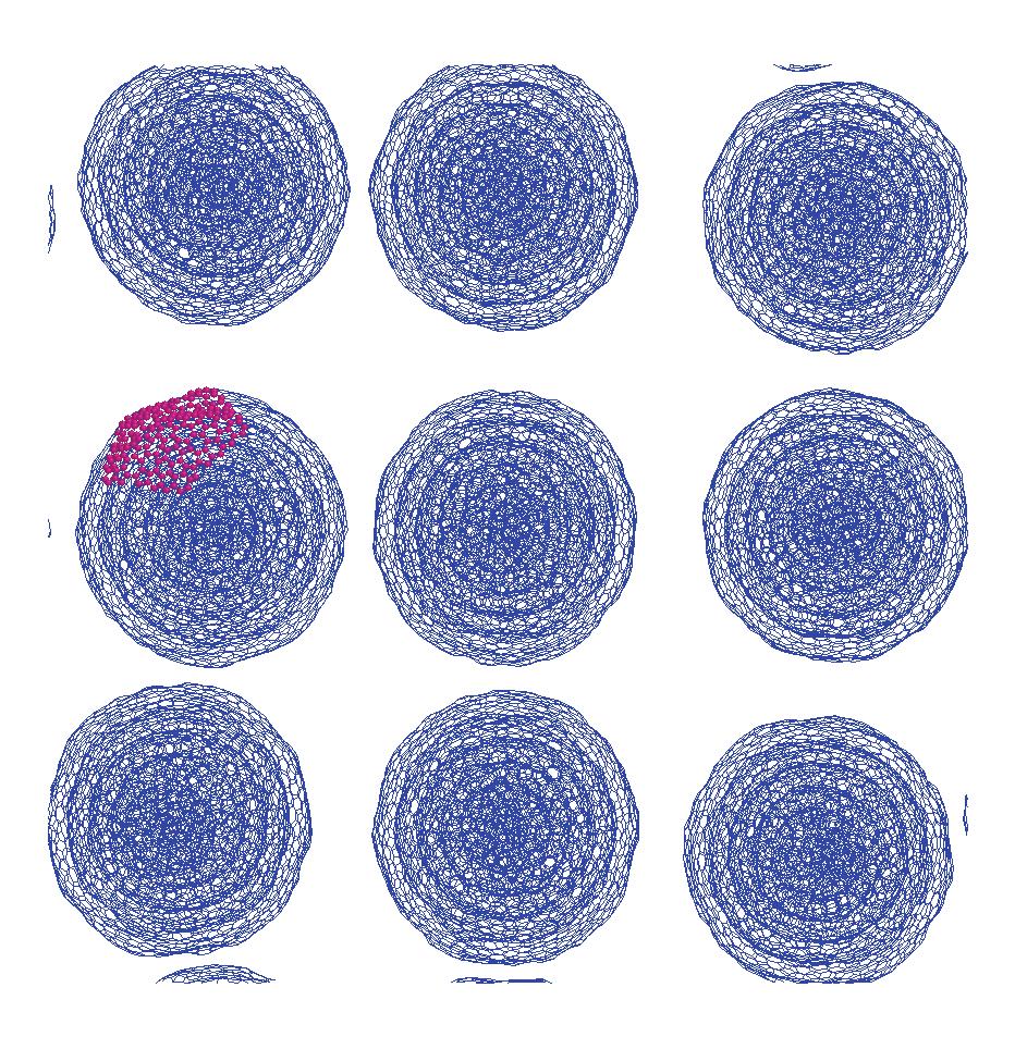
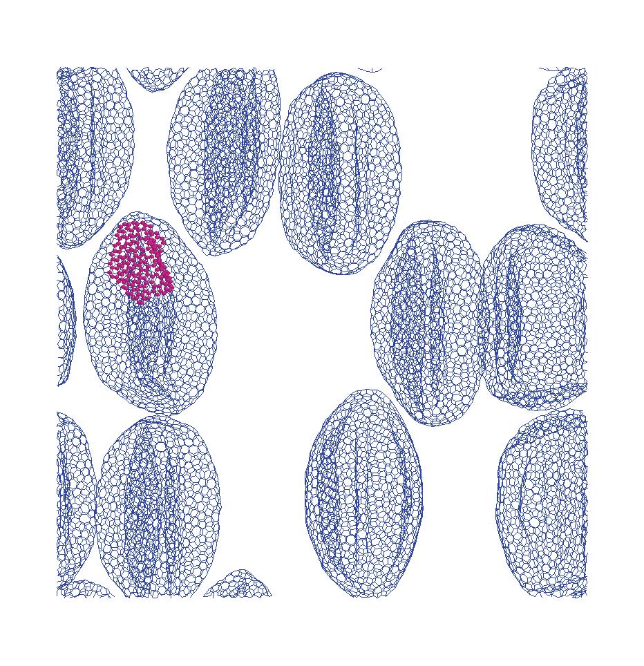
71 5 65 (a) C540 (b) C nm 5.0nm Fig.5.2 Top view of fullerene/olc arra.
72 small serrate C 540 C OLC C 2160 C [nN] 5.2 OLC 3 4 OLC C 2160 < C 2160 < C 540 =.. C 540 C 540 C 540 C 2160 C 2160 OLC Van der Waals (VDW) 5.4 OLC VDW VDW OLC C 540 C 540 C 2160 C OLC ( ) OLC (c) (d) OLC (a) (b) C 2160 C 540 C 540 C 2160 C C 540 C C 540 (7.5[nm])
73 C 540 large serrate C 540 C small serrate small serrate C 2160 C C 540 C 540 C 2160 C large serrate OLC VDW 5.4 C 540 C 540 C 2160 C 2160 VDW 5.4 C 540 C 2160 OLC C 540 C 2160 OLC 5.10 OLC 5.10 (c) (d) OLC OLC VDW 5.10 (a) (c) C 540 C 540 C 540 small serrate C (a) (c) C 540 C 540 (b) (d) C 2160 C 2160 small serrate large serrate C 2160 C 2160 C 540 C
74 5 68 large serrate small serrate VDW 5.3 C 540 C C 540 C 540 small serrate
75 5 69 average= average= Friction coefficient, µ Friction coefficient, µ Displacement of indenter, nm Displacement of indenter, nm (a) C540 Fig.5.3 Friction coefficient - displacement curves under scratch (small serrate indenter). Table 5.2 Indentation depth and friction coefficient (small serrate indenter). model name indentation depth [nm] friction coefficient C 540, small serrate indenter (C 540 -S) C 2160, small serrate indenter (C S) C 540, small serrate indenter ( C 540 -S) C 2160, small serrate indenter ( C S)
76 5 70 (10 5 ) C 540 -S C S 2.0 Number of VDW bonds Displacement of indenter, nm Fig.5.4 Number of VDW bonds - displacement curves under scratch (small serrate indenter). (a) C540-S (b) C2160-S element closeup element closeup Fig.5.5 Snapshots after indentation (small serrate indenter).
77 第5章 薄膜構造での摩擦シミュレーション (a) 0nm scratch (b) 2.5nm scratch (c) 5.0nm scratch (d) 7.5nm scratch Fig.5.6 Snapshots of C540 -S under scratch. (a) 0nm scratch (b) 2.5nm scratch (c) 5.0nm scratch (d) 7.5nm scratch Fig.5.7 Snapshots of C540 -S under scratch. 71
78 5 72 average= average= Friction coefficient, µ 0.1 Friction coefficient, µ Displacement of indenter, nm Displacement of indenter, nm (a) C540 Fig.5.8 Friction coefficient - displacement curves under scratch (large serrate indenter). Table 5.3 Indentation depth and friction coefficient (large serrate indenter). model name indentation depth [nm] friction coefficient C 540, large serrate indenter (C 540 -L) C 2160, large serrate indenter (C L) C 540, large serrate indenter ( C 540 -L) C 2160, large serrate indenter ( C L)
 C540-L (b) C2160-L element closeup element closeup (c) @C540-L (d) @C2160-L Fig.5.10 Snapshots after indentation (large serrate indenter).")
79 5 73 (10 5 ) C 540 -L C L 2.0 Number of VDW bonds Displacement of indenter, nm Fig.5.9 Number of VDW bonds - displacement curves under scratch (large serrate indenter). (a) C540-L (b) C2160-L element closeup element closeup Fig.5.10 Snapshots after indentation (large serrate indenter).
80 第5章 薄膜構造での摩擦シミュレーション (a) 0nm scratch (b) 2.5nm scratch (c) 5.0nm scratch (d) 7.5nm scratch Fig.5.11 Snapshots of C540 -L under scratch. (a) 0nm scratch (b) 2.5nm scratch (c) 5.0nm scratch (d) 7.5nm scratch Fig.5.12 Snapshots of C540 -L under scratch. 74
![5 75 5.2 5.2.1 OLC 5.13 small serrate 80000[fs] OLC 30000[fs] 1nm 14.9nm Fig.5.13 Schematic of simulation model ( C 540, small serrate substrate, small serrate indenter).](/docs-images/109/186975928/images/81-0.jpg "5.2.2 small serrate 5.14 5.14 (d) C 2160 (a) (c) 1.0[nm] small serrate 5.4 5.2")
81 OLC 5.13 small serrate 80000[fs] OLC 30000[fs] 1nm 14.9nm Fig.5.13 Schematic of simulation model ( C 540, small serrate substrate, small serrate indenter) small serrate (d) C 2160 (a) (c) 1.0[nm] small serrate
82 5 76 C 540 C C C C 2160 < C 540 < C 2160 < C C (d) large serrate (b) C (a) (c) (a) C 540 3[nm] (c) (d) OLC C C C C large serrate small serrate
83 large serrate C 2160 small serrate 5.22 C C C 2160 C 540 C 540 C C C 540 C 2160 C C 2160 C 2160
84 5 78 average= average= Friction coefficient, µ Friction coefficient, µ Displacement of indenter, nm Displacement of indenter, nm (a) C540 (b) C2160 average= average= Friction coefficient, µ Friction coefficient, µ Displacement of indenter, nm Displacement of indenter, nm Fig.5.14 Friction coefficient - displacement curves under scratch (small serrate substrate, small serrate indenter).
 2.23 1.")
85 5 79 Table 5.4 Indentation depth and friction coefficient (small serrate substrate, small serrate indenter). model name indentation depth [nm] friction coefficient C 540, small serrate substrate, small serrate indenter (C 540 -SS) C 2160, small serrate substrate, small serrate indenter (C SS) C 540, small serrate substrate, small serrate indenter ( C 540 -SS) C 2160, small serrate substrate, small serrate indenter ( C SS) (a) C540-SS (b) C2160-SS element closeup element closeup Fig.5.15 Snapshots after indentation (small serrate substrate, small serrate indenter).

 5.")


86 第5章 薄膜構造での摩擦シミュレーション 80 (a) 0nm scratch (b) 2.5nm scratch (c) 5.0nm scratch (d) 7.5nm scratch closeup closeup closeup closeup Fig.5.16 Snapshots of C540 -SS under scratch. (a) 0nm scratch (b) 2.5nm scratch (c) 5.0nm scratch (d) 7.5nm scratch closeup closeup closeup Fig.5.17 Snapshots of C2160 -SS under scratch. closeup

 5.")


87 第5章 薄膜構造での摩擦シミュレーション 81 (a) 0nm scratch (b) 2.5nm scratch (c) 5.0nm scratch (d) 7.5nm scratch closeup closeup closeup closeup Fig.5.18 Snapshots of C540 -SS under scratch. (a) 0nm scratch (b) 2.5nm scratch (c) 5.0nm scratch (d) 7.5nm scratch closeup closeup closeup Fig.5.19 Snapshots of C2160 -SS under scratch. closeup
88 5 82 average= average= Friction coefficient, µ 0.2 Friction coefficient, µ Displacement of indenter, nm Displacement of indenter, nm (a) C540 (b) C2160 average= average= Friction coefficient, µ 0.2 Friction coefficient, µ Displacement of indenter, nm Displacement of indenter, nm Fig.5.20 Friction coefficient - displacement curves under scratch (small serrate substrate, large serrate indenter).
89 5 83 Table 5.5 Indentation depth and friction coefficient (small serrate substrate, large serrate indenter). model name indentation depth [nm] friction coefficient C 540, small serrate substrate, large serrate indenter (C 540 -SL) C 2160, small serrate substrate, large serrate indenter (C SL) C 540, small serrate substrate, large serrate indenter ( C 540 -SL) C 2160, small serrate substrate, large serrate indenter ( C SL) (a) C540-SL (b) C2160-SL element closeup element closeup Fig.5.21 Snapshots after indentation (small serrate substrate, large serrate indenter).

 5.")


90 第5章 薄膜構造での摩擦シミュレーション 84 (a) 0nm scratch (b) 2.5nm scratch (c) 5.0nm scratch (d) 7.5nm scratch closeup closeup closeup closeup Fig.5.22 Snapshots of C540 -SL under scratch. (a) 0nm scratch (b) 2.5nm scratch (c) 5.0nm scratch (d) 7.5nm scratch closeup closeup closeup Fig.5.23 Snapshots of C2160 -SL under scratch. closeup
 5.0nm scratch (d) 7.")
 0nm scratch (b) 2.")

91 第5章 薄膜構造での摩擦シミュレーション 85 (a) 0nm scratch (b) 2.5nm scratch (c) 5.0nm scratch (d) 7.5nm scratch closeup closeup closeup closeup Fig.5.24 Snapshots of C540 -SL under scratch. (a) 0nm scratch (b) 2.5nm scratch (c) 5.0nm scratch (d) 7.5nm scratch closeup closeup closeup Fig.5.25 Snapshots of C2160 -SL under scratch. closeup
92 6 OLC OLC, OLC. 2, Stone-Wales 3 C nm 60n 2 n 1 bond. C 540 C 960 C 1500 C
93 OLC 3 OLC OLC C 60 OLC OLC nm+0.5D(D: ) C 960 C OLC C 540 C 2160 C 540 C 2160 ( 2 ) 10 2 C 2160 < C 2160 < C 540 < C C 2160 < C 540 < C 2160 < C 540 OLC
94 6 88 OLC 3 4 ( OLC )
95 [1] Kroto, H.W., Heath,J.R., O Brien, S.C., Curl, R.F., and Smalle, R.E., Nature, 318, (1985), 162. [2] Iijima, S., Nature, 354, (1991), 56. [3] Ugarte, D., Nature, 359, (1992), 707. [4] Kunetsov, V.L., Butenko, Yu.V., Chuvilin, A.L., Romanenko, A.I., Okotrub, A.V., Chem.Phs.Lett., 336, (2001), [5],,, 67, (2001), [6] Kunetsov, V.L., Chuvilin, A.L., Butenko, Yu.V. et al, Chem.Phs.Lett., 222, (1994), 343. [7] Hirata, A., Igarashi, M., Kaito, T., Tribol.Int., 37, (2004), [8] Matsumoto, N., Jol-Pottu, L., Kinoshita, H., Ohmae, N., Diamond.Relat.Mater, 16, (2007), [9] Jol-Pottu, L., Vacher, B., Ohmae, N. et al, Tribol.Lett., 30, (2008), [10] Jol-Pottu, L., Kinoshita, H. et al, Tribol.Int., 41, (2008), [11] Cabioc h, T., Riviere, J.P., Delafond, J., J.Mater.Sci., 30, (1995), [12] Banhart, F., Fuller, T., Redlich, Ph.D., Ajaan, P.M., Chem.Phs.Lett., 269, (1997), [13] Cabioc h, T., Jaouen, M. et al, Appl.Phs.Lett., 73, (1998), [14] (B ) 63, 611, (1997), [15] (B ) 76, 764, (2010),
96 90 [16],,,, 55, (2006), 754. [17] Hirai, Y., et al., Jpn J Appl Phs., 42 6B, (2003), [18] Deguchi, H., Yamaguchi, Y. et al, Chem.Phs.Lett., 503, (2011), [19] 10, 13, (2010). [20] Chico, L., Crespi, V.H., Benedict, L.X., Louie, S.G., Cohen, M.L., Phs.Rev.Lett., 76, 6, (1996), 971. [21] Lee, Y.H., Kim, S.G., Tomanek, D., Phs.Rev.Lett., 78, 12, (1997), [22], (2007), 531,. [23],, (1997), 79,. [24] Saito, R. et al, Chem.Phs.Lett., 195, (1992), [25] Terrones, M. et al, Structural.Chem., 13, (2002), [26] Wang, B.-C., Wang, H.-W., Chang, J.-C., Tso, H.-C., J.Mol.Struct., 540, (2001), [27] Lu, J.P., Yang, W., Phs.Rev.B., 49, 16, (1994), [28] Bakowies, D. et al, J.Am.Chem.Soc., 117, (1995), [29] Jol-Pottu, L., Buchol, E.W., Matsumoto, N. et al, Tribol.Lett., 37, (2010), [30] Buchol, E.W., Phillpot, S.R. et al, Com.Mater.Sci., 54, (2012), [31] Brenner, D.W., Phs.Rev.B., 42, 15, (1990), [32] Ahmadieh, A.A., Rafiadeh, H.A., Phs.Rev.B., 7, (1973), [33],, (1990),. [34] (2011).
97 OLC 1 ( 16 ),, (2011.5) OLC 24 CMD2011,, ( ) 25 CMD2012,, ( ) 91
98 92
99 93
100 94
101 95
102 96
103 97
104 98
105 ( ) ( )
1 1.1,,,.. (, ),..,. (Fig. 1.1). Macro theory (e.g. Continuum mechanics) Consideration under the simple concept (e.g. ionic radius, bond valence) Stru
,..,. (Fig. 1.1). Macro theory (e.g. Continuum mechanics) Consideration under the simple concept (e.g. ionic radius, bond valence) Stru") 1. 1-1. 1-. 1-3.. MD -1. -. -3. MD 1 1 1.1,,,.. (, ),..,. (Fig. 1.1). Macro theory (e.g. Continuum mechanics) Consideration under the simple concept (e.g. ionic radius, bond valence) Structural relaxation
1. 1-1. 1-. 1-3.. MD -1. -. -3. MD 1 1 1.1,,,.. (, ),..,. (Fig. 1.1). Macro theory (e.g. Continuum mechanics) Consideration under the simple concept (e.g. ionic radius, bond valence) Structural relaxation
Study on Application of the cos a Method to Neutron Stress Measurement Toshihiko SASAKI*3 and Yukio HIROSE Department of Materials Science and Enginee
 Study on Application of the cos a Method to Neutron Stress Measurement Toshihiko SASAKI*3 and Yukio HIROSE Department of Materials Science and Engineering, Kanazawa University, Kakuma-machi, Kanazawa-shi,
Note; a: Pressure sensor, b: Semi-permeable membrane, c: O-ring, d: Support screen, e: Solution, f: Solvent. Fig. 2. Osmometer cell. Fig. 1. Schematic
 Studies on Collapse of Wood Cells and Negative Pressure in Cell Lumen by Yoshiaki HATTORI* and Yasushi KANAGAWA** The negative pressure, that is liquid-tension, to cause cell-collapse was estimated with
14 FEM [1] 1992 [3] 1(a)(b) 1(c) [2] 2 ( 財 ) 日本海事協会 36 平成 14 年度 ClassNK 研究発表会
![14 FEM [1] 1992 [3] 1(a)(b) 1(c) [2] 2 ( 財 ) 日本海事協会 36 平成 14 年度 ClassNK 研究発表会](/thumbs/92/109274181.jpg "14 FEM [1] 1992 [3] 1(a)(b) 1(c) [2] 2 ( 財 ) 日本海事協会 36 平成 14 年度 ClassNK 研究発表会") 1. 1(1) 1(2)[1] 1992 [2] 1992 [3] 100 100 比率 (%) 80 60 40 変形腐食亀裂 相対損傷数 80 60 40 変形腐食亀裂 20 20 0 0 5 10 15 20 25 船齢 ( 年 ) 0 0 5 10 15 20 25 船齢 ( 年 ) (1) Ratio of Each Damage (2) Number of Damage Fig.1 Relation
1. 1(1) 1(2)[1] 1992 [2] 1992 [3] 100 100 比率 (%) 80 60 40 変形腐食亀裂 相対損傷数 80 60 40 変形腐食亀裂 20 20 0 0 5 10 15 20 25 船齢 ( 年 ) 0 0 5 10 15 20 25 船齢 ( 年 ) (1) Ratio of Each Damage (2) Number of Damage Fig.1 Relation
6) , 3) L60m h=4m 4m φ19 SS400 σ y = kn/mm 2 E = 205.8kN/mm 2 Table1 4) 7 Fig.1 5 7) S S 2 5 (Fig.2 ) ( No.1, No.2, No.3, No.4)
 , 3) L60m h=4m 4m φ19 SS400 σ y = kn/mm 2 E = 205.8kN/mm 2 Table1 4) 7 Fig.1 5 7) S S 2 5 (Fig.2 ) ( No.1, No.2, No.3, No.4)") Damages and Earthquake Resistant Performance of Steel Frame Structures with Self Strain Stress (Faculty of Architecture and Structural Engineering) Yutaka NIHO, Masaru TERAOKA (Professor Emeritus of KNCT)
Damages and Earthquake Resistant Performance of Steel Frame Structures with Self Strain Stress (Faculty of Architecture and Structural Engineering) Yutaka NIHO, Masaru TERAOKA (Professor Emeritus of KNCT)
1..FEM FEM 3. 4.
 008 stress behavior at the joint of stringer to cross beam of the steel railway bridge 1115117 1..FEM FEM 3. 4. ABSTRACT 1. BackgroundPurpose The occurrence of fatigue crack is reported in the joint of
42 1 Fig. 2. Li 2 B 4 O 7 crystals with 3inches and 4inches in diameter. Fig. 4. Transmission curve of Li 2 B 4 O 7 crystal. Fig. 5. Refractive index
 MEMOIRS OF SHONAN INSTITUTE OF TECHNOLOGY Vol. 42, No. 1, 2008 Li 2 B 4 O 7 (LBO) *, ** * ** ** Optical Scatterer and Crystal Growth Technology of LBO Single Crystal For Development with Optical Application
chap1_MDpotentials.ppt
 simplest Morse : simplest (1 Well-chosen functional form is more useful than elaborate fitting strategies!! Phys. Rev. 34, 57 (1929 ( 2 E ij = D e 1" exp("#(r ij " r e 2 r ij = r i " r j r ij =r e E ij
Fig. 4. Configuration of fatigue test specimen. Table I. Mechanical property of test materials. Table II. Full scale fatigue test conditions and test
 (J. Soc. Mat. Sci., Japan), Vol. 52, No. 11, pp. 1351-1356, Nov. 2003 Fatigue Life Prediction of Coiled Tubing by Takanori KATO*, Miyuki YAMAMOTO*, Isao SAWAGUCHI** and Tetsuo YONEZAWA*** Coiled tubings,
28 Horizontal angle correction using straight line detection in an equirectangular image
 28 Horizontal angle correction using straight line detection in an equirectangular image 1170283 2017 3 1 2 i Abstract Horizontal angle correction using straight line detection in an equirectangular image
The Evaluation of LBB Behavior and Crack Opening Displacement on Statically Indeterminate Piping System Subjected to Monotonic Load The plastic collap
 The Evaluation of LBB Behavior and Crack Opening Displacement on Statically Indeterminate Piping System Subjected to Monotonic Load The plastic collapse and LBB behavior of statically indeterminate piping
JFE.dvi
 ,, Department of Civil Engineering, Chuo University Kasuga 1-13-27, Bunkyo-ku, Tokyo 112 8551, JAPAN E-mail : atsu1005@kc.chuo-u.ac.jp E-mail : kawa@civil.chuo-u.ac.jp SATO KOGYO CO., LTD. 12-20, Nihonbashi-Honcho
The Effect of the Circumferential Temperature Change on the Change in the Strain Energy of Carbon Steel during the Rotatory Bending Fatigue Test by Ch
 The Effect of the Circumferential Temperature Change on the Change in the Strain Energy of Carbon Steel during the Rotatory Bending Fatigue Test by Chikara MINAMISAWA, Nozomu AOKI (Department of Mechanical
 [Ver. 0.2] 1 2 3 4 5 6 7 1 1.1 1.2 1.3 1.4 1.5 1 1.1 1 1.2 1. (elasticity) 2. (plasticity) 3. (strength) 4. 5. (toughness) 6. 1 1.2 1. (elasticity) } 1 1.2 2. (plasticity), 1 1.2 3. (strength) a < b F
鉄筋単体の座屈モデル(HP用).doc
.doc") RC uckling elastic uckling of initiall ent memer full-plastic ultimate elasto-plastic uckling model cover concrete initial imperfection 1 Fixed-fixed Hinged-hinged x x M M 1 3 1 a π = 1 cos x πx = a sin
RC uckling elastic uckling of initiall ent memer full-plastic ultimate elasto-plastic uckling model cover concrete initial imperfection 1 Fixed-fixed Hinged-hinged x x M M 1 3 1 a π = 1 cos x πx = a sin
Journal of Japan Institute of Light Metals, Vol. 58, No. 2 (2008), pp
, pp") 58 00847 53 * ** ** Journal of Japan Institute of Light Metals, Vol. 58, No. 008, pp. 47 53 Production of aluminum tall container with flange by hydraulic bulging with compression of surrounding material
58 00847 53 * ** ** Journal of Japan Institute of Light Metals, Vol. 58, No. 008, pp. 47 53 Production of aluminum tall container with flange by hydraulic bulging with compression of surrounding material
1 2 3
 INFORMATION FOR THE USER DRILL SELECTION CHART CARBIDE DRILLS NEXUS DRILLS DIAMOND DRILLS VP-GOLD DRILLS TDXL DRILLS EX-GOLD DRILLS V-GOLD DRILLS STEEL FRAME DRILLS HARD DRILLS V-SELECT DRILLS SPECIAL
電子部品はんだ接合部の熱疲労寿命解析
 43 Evaluation for Thermal Fatigue Life of Solder Joints in Electronic Components Haruhiko Yamada, Kazuyoshi Ogawa 2 63Sn- 37Pb 95Pb-5Sn Si Cu Si 63Sn-37Pb Since automotive electronic components are used
日立金属技報 Vol.34
 Influence of Misorientation Angle between Adjacent Grains on Magnetization Reversal in Nd-Fe-B Sintered Magnet Tomohito Maki Rintaro Ishii Mitsutoshi Natsumeda Takeshi Nishiuchi Ryo Uchikoshi Masaaki Takezawa
Developement of Plastic Collocation Method Extension of Plastic Node Method by Yukio Ueda, Member Masahiko Fujikubo, Member Masahiro Miura, Member Sum
 Developement of Plastic Collocation Method Extension of Plastic Node Method by Yukio Ueda, Member Masahiko Fujikubo, Member Masahiro Miura, Member Summary Previously, the authors developed the plastic
T05_Nd-Fe-B磁石.indd
 Influence of Intergranular Grain Boundary Phases on Coercivity in Nd-Fe-B-based Magnets Takeshi Nishiuchi Teruo Kohashi Isao Kitagawa Akira Sugawara Hiroyuki Yamamoto To determine how to increase the coercivity
Development of Induction and Exhaust Systems for Third-Era Honda Formula One Engines Induction and exhaust systems determine the amount of air intake
 Development of Induction and Exhaust Systems for Third-Era Honda Formula One Engines Induction and exhaust systems determine the amount of air intake supplied to the engine, and as such are critical elements
1: A/B/C/D Fig. 1 Modeling Based on Difference in Agitation Method artisoc[7] A D 2017 Information Processing
![1: A/B/C/D Fig. 1 Modeling Based on Difference in Agitation Method artisoc[7] A D 2017 Information Processing](/thumbs/88/115893223.jpg "1: A/B/C/D Fig. 1 Modeling Based on Difference in Agitation Method artisoc[7] A D 2017 Information Processing") 1,a) 2,b) 3 Modeling of Agitation Method in Automatic Mahjong Table using Multi-Agent Simulation Hiroyasu Ide 1,a) Takashi Okuda 2,b) Abstract: Automatic mahjong table refers to mahjong table which automatically
1,a) 2,b) 3 Modeling of Agitation Method in Automatic Mahjong Table using Multi-Agent Simulation Hiroyasu Ide 1,a) Takashi Okuda 2,b) Abstract: Automatic mahjong table refers to mahjong table which automatically
Continuous Cooling Transformation Diagrams for Welding of Mn-Si Type 2H Steels. Harujiro Sekiguchi and Michio Inagaki Synopsis: The authors performed
 Continuous Cooling Transformation Diagrams for Welding of Mn-Si Type 2H Steels. Harujiro Sekiguchi and Michio Inagaki Synopsis: The authors performed a series of researches on continuous cooling transformation
 840 Geographical Review of Japan 73A-12 835-854 2000 The Mechanism of Household Reproduction in the Fishing Community on Oro Island Masakazu YAMAUCHI (Graduate Student, Tokyo University) This
第62巻 第1号 平成24年4月/石こうを用いた木材ペレット
 Bulletin of Japan Association for Fire Science and Engineering Vol. 62. No. 1 (2012) Development of Two-Dimensional Simple Simulation Model and Evaluation of Discharge Ability for Water Discharge of Firefighting
H17-NIIT研究報告
 DLC SiC 1 2 3 4 4 5 5 6 The Influence of SiC Shot Blasting on Adhesion of DLC Film MIKI Yasuhiro *1), TANIGUCHI Tadashi *2), MATSUOKA Takashi *3) SASAKI Kenji *4), FUKUSHI Takayoshi *4), YUKI Tamotsu *5),
16 (16) poly-si mJ/cm 2 ELA poly-si super cooled liquid, SCL [3] a-si poly-si [4] solid phase crystalization, SPC [5] mJ/cm 2 SPC SCL (di
![16 (16) poly-si mJ/cm 2 ELA poly-si super cooled liquid, SCL [3] a-si poly-si [4] solid phase crystalization, SPC [5] mJ/cm 2 SPC SCL (di](/thumbs/82/84964999.jpg "16 (16) poly-si mJ/cm 2 ELA poly-si super cooled liquid, SCL [3] a-si poly-si [4] solid phase crystalization, SPC [5] mJ/cm 2 SPC SCL (di") (15) 15 ELA により形成された poly-si 結晶成長様式 - グレイン形状と水素の関係 - Crystal Growth Mode of Poly-Si Prepared by ELA -Relationship between the Grain Morphology and ydrogens- Naoya KAWAMOTO (Dept. of Electrical and Electronic
(15) 15 ELA により形成された poly-si 結晶成長様式 - グレイン形状と水素の関係 - Crystal Growth Mode of Poly-Si Prepared by ELA -Relationship between the Grain Morphology and ydrogens- Naoya KAWAMOTO (Dept. of Electrical and Electronic
走査型プローブ顕微鏡によるラテックス/デンプンブレンドフィルムの相分離状態の観察
 紙パ技協誌, 53(3): 107-113(1999) * 1 Observation of Separated Domains in SB-latex/Starch blend film by Scanning Probe Microscope Toshiharu Enomae and Fumihiko Onabe Graduate School of Agricultural and Life
<8B5A8F70985F95B632936EE7B22E696E6464>
 47 Electrical Discharge Truing for Electroplated Diamond Tools Koji Watanabe Hisashi Minami Hatsumi Hiramatsu Kiyonori Masui (211 7 8 ) Electroplated diamond tools are widely used for grinding because
卒業論文
 Cu-Ru ...7 1.1....7 1.2....7 1.3....8...9 2.1....9 2.1.1....9 2.1.2....10 2.2.... 11 2.2.1.... 11 2.2.2. ()...12 2.2.3. ()...13 2.2....15...18 3.1. Cu z ...18 3.1.1....18 3.1.2....19 3.1.3....29 3.2.
perature was about 2.5 Ž higher than that of the control irrespective of wind speed. With increasing wind speeds of more than 1m/s, the leaf temperatu
 Studies on the Row Covering Methods of Vinylon Cheesecloth to Prevent Cold Injury in Cabbage Daizou IGARASHI*, Masumi OKADA** and Keiichl NAKAYAMA*** *Miura Branch, Kanagawa Horticultural Experiment Station,
1. 2 P 2 (x, y) 2 x y (0, 0) R 2 = {(x, y) x, y R} x, y R P = (x, y) O = (0, 0) OP ( ) OP x x, y y ( ) x v = y ( ) x 2 1 v = P = (x, y) y ( x y ) 2 (x
 2 x y (0, 0) R 2 = {(x, y) x, y R} x, y R P = (x, y) O = (0, 0) OP ( ) OP x x, y y ( ) x v = y ( ) x 2 1 v = P = (x, y) y ( x y ) 2 (x") . P (, (0, 0 R {(,, R}, R P (, O (0, 0 OP OP, v v P (, ( (, (, { R, R} v (, (, (,, z 3 w z R 3,, z R z n R n.,..., n R n n w, t w ( z z Ke Words:. A P 3 0 B P 0 a. A P b B P 3. A π/90 B a + b c π/ 3. +
. P (, (0, 0 R {(,, R}, R P (, O (0, 0 OP OP, v v P (, ( (, (, { R, R} v (, (, (,, z 3 w z R 3,, z R z n R n.,..., n R n n w, t w ( z z Ke Words:. A P 3 0 B P 0 a. A P b B P 3. A π/90 B a + b c π/ 3. +
Vol. 12 ( ) Mirifusus Evolution of Radiolarian Mirifusus (Marine Plankton) and Mechanical Optimization of Frame Structure Structual Mechanichal
 Mirifusus Evolution of Radiolarian Mirifusus (Marine Plankton) and Mechanical Optimization of Frame Structure Structual Mechanichal") Vol. (009 8 ) Mirifusus Evolution of Radiolarian Mirifusus (Marine Plankton) and Mechanical Optimization of Frame Structure Structual Mechanichal Verification of Succession of Its Skeleton Shape Takashi
Vol. (009 8 ) Mirifusus Evolution of Radiolarian Mirifusus (Marine Plankton) and Mechanical Optimization of Frame Structure Structual Mechanichal Verification of Succession of Its Skeleton Shape Takashi
1 Fig. 1 Extraction of motion,.,,, 4,,, 3., 1, 2. 2.,. CHLAC,. 2.1,. (256 ).,., CHLAC. CHLAC, HLAC. 2.3 (HLAC ) r,.,. HLAC. N. 2 HLAC Fig. 2
.,., CHLAC. CHLAC, HLAC. 2.3 (HLAC ) r,.,. HLAC. N. 2 HLAC Fig. 2") CHLAC 1 2 3 3,. (CHLAC), 1).,.,, CHLAC,.,. Suspicious Behavior Detection based on CHLAC Method Hideaki Imanishi, 1 Toyohiro Hayashi, 2 Shuichi Enokida 3 and Toshiaki Ejima 3 We have proposed a method for
CHLAC 1 2 3 3,. (CHLAC), 1).,.,, CHLAC,.,. Suspicious Behavior Detection based on CHLAC Method Hideaki Imanishi, 1 Toyohiro Hayashi, 2 Shuichi Enokida 3 and Toshiaki Ejima 3 We have proposed a method for
Fig. 1. Schematic drawing of testing system. 71 ( 1 )
") 1850 UDC 669.162.283 : 669.162.263.24/. 25 Testing Method of High Temperature Properties of Blast Furnace Burdens Yojiro YAMAOKA, Hirohisa HOTTA, and Shuji KAJIKAWA Synopsis : Regarding the reduction under
1850 UDC 669.162.283 : 669.162.263.24/. 25 Testing Method of High Temperature Properties of Blast Furnace Burdens Yojiro YAMAOKA, Hirohisa HOTTA, and Shuji KAJIKAWA Synopsis : Regarding the reduction under
4/15 No.
 4/15 No. 1 4/15 No. 4/15 No. 3 Particle of mass m moving in a potential V(r) V(r) m i ψ t = m ψ(r,t)+v(r)ψ(r,t) ψ(r,t) = ϕ(r)e iωt ψ(r,t) Wave function steady state m ϕ(r)+v(r)ϕ(r) = εϕ(r) Eigenvalue problem
Fig. 3 Flow diagram of image processing. Black rectangle in the photo indicates the processing area (128 x 32 pixels).
.") Fig. 1 The scheme of glottal area as a function of time Fig. 3 Flow diagram of image processing. Black rectangle in the photo indicates the processing area (128 x 32 pixels). Fig, 4 Parametric representation
Fig. 1 The scheme of glottal area as a function of time Fig. 3 Flow diagram of image processing. Black rectangle in the photo indicates the processing area (128 x 32 pixels). Fig, 4 Parametric representation
24 Depth scaling of binocular stereopsis by observer s own movements
 24 Depth scaling of binocular stereopsis by observer s own movements 1130313 2013 3 1 3D 3D 3D 2 2 i Abstract Depth scaling of binocular stereopsis by observer s own movements It will become more usual
70 : 20 : A B (20 ) (30 ) 50 1
 (30 ) 50 1") 70 : 0 : A B (0 ) (30 ) 50 1 1 4 1.1................................................ 5 1. A............................................... 6 1.3 B............................................... 7 8.1 A...............................................
70 : 0 : A B (0 ) (30 ) 50 1 1 4 1.1................................................ 5 1. A............................................... 6 1.3 B............................................... 7 8.1 A...............................................
19 σ = P/A o σ B Maximum tensile strength σ % 0.2% proof stress σ EL Elastic limit Work hardening coefficient failure necking σ PL Proportional
 19 σ = P/A o σ B Maximum tensile strength σ 0. 0.% 0.% proof stress σ EL Elastic limit Work hardening coefficient failure necking σ PL Proportional limit ε p = 0.% ε e = σ 0. /E plastic strain ε = ε e
+ 1 ( ) I IA i i i 1 n m a 11 a 1j a 1m A = a i1 a ij a im a n1 a nj a nm.....
 I IA i i i 1 n m a 11 a 1j a 1m A = a i1 a ij a im a n1 a nj a nm.....") + http://krishnathphysaitama-uacjp/joe/matrix/matrixpdf 1 ( ) I IA i i i 1 n m a 11 a 1j a 1m A = a i1 a ij a im a n1 a nj a nm (1) n m () (n, m) ( ) n m B = ( ) 3 2 4 1 (2) 2 2 ( ) (2, 2) ( ) C = ( 46
+ http://krishnathphysaitama-uacjp/joe/matrix/matrixpdf 1 ( ) I IA i i i 1 n m a 11 a 1j a 1m A = a i1 a ij a im a n1 a nj a nm (1) n m () (n, m) ( ) n m B = ( ) 3 2 4 1 (2) 2 2 ( ) (2, 2) ( ) C = ( 46
untitled
 SPring-8 RFgun JASRI/SPring-8 6..7 Contents.. 3.. 5. 6. 7. 8. . 3 cavity γ E A = er 3 πε γ vb r B = v E c r c A B A ( ) F = e E + v B A A A A B dp e( v B+ E) = = m d dt dt ( γ v) dv e ( ) dt v B E v E
128 3 II S 1, S 2 Φ 1, Φ 2 Φ 1 = { B( r) n( r)}ds S 1 Φ 2 = { B( r) n( r)}ds (3.3) S 2 S S 1 +S 2 { B( r) n( r)}ds = 0 (3.4) S 1, S 2 { B( r) n( r)}ds
 n( r)}ds S 1 Φ 2 = { B( r) n( r)}ds (3.3) S 2 S S 1 +S 2 { B( r) n( r)}ds = 0 (3.4) S 1, S 2 { B( r) n( r)}ds") 127 3 II 3.1 3.1.1 Φ(t) ϕ em = dφ dt (3.1) B( r) Φ = { B( r) n( r)}ds (3.2) S S n( r) Φ 128 3 II S 1, S 2 Φ 1, Φ 2 Φ 1 = { B( r) n( r)}ds S 1 Φ 2 = { B( r) n( r)}ds (3.3) S 2 S S 1 +S 2 { B( r) n( r)}ds
127 3 II 3.1 3.1.1 Φ(t) ϕ em = dφ dt (3.1) B( r) Φ = { B( r) n( r)}ds (3.2) S S n( r) Φ 128 3 II S 1, S 2 Φ 1, Φ 2 Φ 1 = { B( r) n( r)}ds S 1 Φ 2 = { B( r) n( r)}ds (3.3) S 2 S S 1 +S 2 { B( r) n( r)}ds
塗装深み感の要因解析
 17 Analysis of Factors for Paint Depth Feeling Takashi Wada, Mikiko Kawasumi, Taka-aki Suzuki ( ) ( ) ( ) The appearance and quality of objects are controlled by paint coatings on the surfaces of the objects.
 B 1 B.1.......................... 1 B.1.1................. 1 B.1.2................. 2 B.2........................... 5 B.2.1.......................... 5 B.2.2.................. 6 B.2.3..................
5b_08.dvi
 , Circularly Polarized Patch Antennas Combining Different Shaped Linealy Polarized Elements Takanori NORO,, Yasuhiro KAZAMA, Masaharu TAKAHASHI, and Koichi ITO 1. GPS LAN 10% [1] Graduate School of Science
Study on Throw Accuracy for Baseball Pitching Machine with Roller (Study of Seam of Ball and Roller) Shinobu SAKAI*5, Juhachi ODA, Kengo KAWATA and Yu
 Shinobu SAKAI*5, Juhachi ODA, Kengo KAWATA and Yu") Study on Throw Accuracy for Baseball Pitching Machine with Roller (Study of Seam of Ball and Roller) Shinobu SAKAI*5, Juhachi ODA, Kengo KAWATA and Yuichiro KITAGAWA Department of Human and Mechanical
Study on Throw Accuracy for Baseball Pitching Machine with Roller (Study of Seam of Ball and Roller) Shinobu SAKAI*5, Juhachi ODA, Kengo KAWATA and Yuichiro KITAGAWA Department of Human and Mechanical
06_学術.indd
 Arts and Sciences Development and usefulness evaluation of a remote control pressured pillow for prone position 1 36057 2 45258 2 29275 3 3 4 1 2 3 4 Key words: pressured pillow prone position, stomach
レーザ誘起蛍光法( LIF法) によるピストンの油膜挙動の解析
 によるピストンの油膜挙動の解析") Analysis of Piston Oil Film Behavior by Using Laser Induced Fluorescence Method Shuzou Sanda, Akinori Saito ( Laser Induced Fluorescence Method LIF ) LIF Scanning -LIF Abstract Analysis of the oil film
Analysis of Piston Oil Film Behavior by Using Laser Induced Fluorescence Method Shuzou Sanda, Akinori Saito ( Laser Induced Fluorescence Method LIF ) LIF Scanning -LIF Abstract Analysis of the oil film
06_学術_関節単純X線画像における_1c_梅木様.indd
 Arts and Sciences X The formulation of femoral heard measurement corrected enlargement ratio using hip joints X-ray Imaging 1 2 1 1 1 2 Key words: Bipolar Hip Arthroplasty (BHA) Preoperative planning Enlargement
Hanbury-Brown Twiss (ver. 2.0) van Cittert - Zernike mutual coherence
 van Cittert - Zernike mutual coherence") Hanbury-Brown Twiss (ver. 2.) 25 4 4 1 2 2 2 2.1 van Cittert - Zernike..................................... 2 2.2 mutual coherence................................. 4 3 Hanbury-Brown Twiss ( ) 5 3.1............................................
Hanbury-Brown Twiss (ver. 2.) 25 4 4 1 2 2 2 2.1 van Cittert - Zernike..................................... 2 2.2 mutual coherence................................. 4 3 Hanbury-Brown Twiss ( ) 5 3.1............................................
 Housing Purchase by Single Women in Tokyo Yoshilehl YUI* Recently some single women purchase their houses and the number of houses owned by single women are increasing in Tokyo. And their housing demands
鉄鋼協会プレゼン
 NN :~:, 8 Nov., Adaptive H Control for Linear Slider with Friction Compensation positioning mechanism moving table stand manipulator Point to Point Control [G] Continuous Path Control ground Fig. Positoining
Table 1 Properties of Shrink Films on Market Fig. 2 Comparison of Shrinkage curves of PS and PET films. Fig. 3 Schematic diagram of "Variations in bot
 Bowing Reduction in Biaxial Stretching Process of Styrenic Shrink Film and Its Properties YAMADA Hirofumi TAKEI Toshio and MORITA Tsuyoshi Trimming weight of PET bottle is tried from the trends of aseptic
(1.2) T D = 0 T = D = 30 kn 1.2 (1.4) 2F W = 0 F = W/2 = 300 kn/2 = 150 kn 1.3 (1.9) R = W 1 + W 2 = = 1100 N. (1.9) W 2 b W 1 a = 0
 T D = 0 T = D = 30 kn 1.2 (1.4) 2F W = 0 F = W/2 = 300 kn/2 = 150 kn 1.3 (1.9) R = W 1 + W 2 = = 1100 N. (1.9) W 2 b W 1 a = 0") 1 1 1.1 1.) T D = T = D = kn 1. 1.4) F W = F = W/ = kn/ = 15 kn 1. 1.9) R = W 1 + W = 6 + 5 = 11 N. 1.9) W b W 1 a = a = W /W 1 )b = 5/6) = 5 cm 1.4 AB AC P 1, P x, y x, y y x 1.4.) P sin 6 + P 1 sin 45
1 1 1.1 1.) T D = T = D = kn 1. 1.4) F W = F = W/ = kn/ = 15 kn 1. 1.9) R = W 1 + W = 6 + 5 = 11 N. 1.9) W b W 1 a = a = W /W 1 )b = 5/6) = 5 cm 1.4 AB AC P 1, P x, y x, y y x 1.4.) P sin 6 + P 1 sin 45
平常時火災における消火栓の放水能力に関する研究
 Discharge Ability of Hydrant to Ordinary Fire Yoshiro Namba *1,Kenjiro Yasuno *2,Yoshiteru Murosaki *3,Akihiko Hokugo *4, Masahiro Fujiwara *5, Akihiro Kasuya *6,Hideo Matsuoka* 7 * 1 Department of Architecture,
The Evaluation on Impact Strength of Structural Elements by Means of Drop Weight Test Elastic Response and Elastic Limit by Hiroshi Maenaka, Member Sh
 The Evaluation on Impact Strength of Structural Elements by Means of Drop Weight Test Elastic Response and Elastic Limit by Hiroshi Maenaka, Member Shigeru Kitamura, Member Masaaki Sakuma Genya Aoki, Member
A Higher Weissenberg Number Analysis of Die-swell Flow of Viscoelastic Fluids Using a Decoupled Finite Element Method Iwata, Shuichi * 1/Aragaki, Tsut
 A Higher Weissenberg Number Analysis of Die-swell Flow of Viscoelastic Fluids Using a Decoupled Finite Element Method Iwata, Shuichi * 1/Aragaki, Tsutomu * 1/Mori, Hideki * 1 Ishikawa, Satoshi * 1/Shin,
( ; ) C. H. Scholz, The Mechanics of Earthquakes and Faulting : - ( ) σ = σ t sin 2π(r a) λ dσ d(r a) =
 C. H. Scholz, The Mechanics of Earthquakes and Faulting : - ( ) σ = σ t sin 2π(r a) λ dσ d(r a) =") 1 9 8 1 1 1 ; 1 11 16 C. H. Scholz, The Mechanics of Earthquakes and Faulting 1. 1.1 1.1.1 : - σ = σ t sin πr a λ dσ dr a = E a = π λ σ πr a t cos λ 1 r a/λ 1 cos 1 E: σ t = Eλ πa a λ E/π γ : λ/ 3 γ =
1 9 8 1 1 1 ; 1 11 16 C. H. Scholz, The Mechanics of Earthquakes and Faulting 1. 1.1 1.1.1 : - σ = σ t sin πr a λ dσ dr a = E a = π λ σ πr a t cos λ 1 r a/λ 1 cos 1 E: σ t = Eλ πa a λ E/π γ : λ/ 3 γ =
388599-P036-P041
 Die life improvement of flat type punches for hot forging Morihiko Nakasaki, Koji Era, Hiroyuki Myochin and Ichiro Takasu Synopsis: Since forged products have been required more complex and net-shape,
2 1 ( ) 2 ( ) i
 2 ( ) i") 21 Perceptual relation bettween shadow, reflectance and luminance under aambiguous illuminations. 1100302 2010 3 1 2 1 ( ) 2 ( ) i Abstract Perceptual relation bettween shadow, reflectance and luminance
21 Perceptual relation bettween shadow, reflectance and luminance under aambiguous illuminations. 1100302 2010 3 1 2 1 ( ) 2 ( ) i Abstract Perceptual relation bettween shadow, reflectance and luminance
Motivation and Purpose There is no definition about whether seatbelt anchorage should be fixed or not. We tested the same test conditions except for t
 Review of Seatbelt Anchorage and Dimensions of Test Bench Seat Cushion JASIC Motivation and Purpose There is no definition about whether seatbelt anchorage should be fixed or not. We tested the same test
85 4
 85 4 86 Copright c 005 Kumanekosha 4.1 ( ) ( t ) t, t 4.1.1 t Step! (Step 1) (, 0) (Step ) ±V t (, t) I Check! P P V t π 54 t = 0 + V (, t) π θ : = θ : π ) θ = π ± sin ± cos t = 0 (, 0) = sin π V + t +V
A = A x x + A y y + A, B = B x x + B y y + B, C = C x x + C y y + C..6 x y A B C = A x x + A y y + A B x B y B C x C y C { B = A x x + A y y + A y B B
 9 7 A = A x x + A y y + A, B = B x x + B y y + B, C = C x x + C y y + C..6 x y A B C = A x x + A y y + A B x B y B C x C y C { B = A x x + A y y + A y B B x x B } B C y C y + x B y C x C C x C y B = A
) ] [ h m x + y + + V x) φ = Eφ 1) z E = i h t 13) x << 1) N n n= = N N + 1) 14) N n n= = N N + 1)N + 1) 6 15) N n 3 n= = 1 4 N N + 1) 16) N n 4
![) ] [ h m x + y + + V x) φ = Eφ 1) z E = i h t 13) x << 1) N n n= = N N + 1) 14) N n n= = N N + 1)N + 1) 6 15) N n 3 n= = 1 4 N N + 1) 16) N n 4](/thumbs/92/107866707.jpg ") ] [ h m x + y + + V x) φ = Eφ 1) z E = i h t 13) x << 1) N n n= = N N + 1) 14) N n n= = N N + 1)N + 1) 6 15) N n 3 n= = 1 4 N N + 1) 16) N n 4") 1. k λ ν ω T v p v g k = π λ ω = πν = π T v p = λν = ω k v g = dω dk 1) ) 3) 4). p = hk = h λ 5) E = hν = hω 6) h = h π 7) h =6.6618 1 34 J sec) hc=197.3 MeV fm = 197.3 kev pm= 197.3 ev nm = 1.97 1 3 ev
1. k λ ν ω T v p v g k = π λ ω = πν = π T v p = λν = ω k v g = dω dk 1) ) 3) 4). p = hk = h λ 5) E = hν = hω 6) h = h π 7) h =6.6618 1 34 J sec) hc=197.3 MeV fm = 197.3 kev pm= 197.3 ev nm = 1.97 1 3 ev
δf = δn I [ ( FI (N I ) N I ) T,V δn I [ ( FI N I ( ) F N T,V ( ) FII (N N I ) + N I ) ( ) FII T,V N II T,V T,V ] ] = 0 = 0 (8.2) = µ (8.3) G
![δf = δn I [ ( FI (N I ) N I ) T,V δn I [ ( FI N I ( ) F N T,V ( ) FII (N N I ) + N I ) ( ) FII T,V N II T,V T,V ] ] = 0 = 0 (8.2) = µ (8.3) G](/thumbs/91/106215968.jpg "δf = δn I [ ( FI (N I ) N I ) T,V δn I [ ( FI N I ( ) F N T,V ( ) FII (N N I ) + N I ) ( ) FII T,V N II T,V T,V ] ] = 0 = 0 (8.2) = µ (8.3) G") 8 ( ) 8. 1 ( ) F F = F I (N I, T, V I ) + F II (N II, T, V II ) (8.1) F δf = δn I [ ( FI (N I ) N I 8. 1 111 ) T,V δn I [ ( FI N I ( ) F N T,V ( ) FII (N N I ) + N I ) ( ) FII T,V N II T,V T,V ] ] = 0
8 ( ) 8. 1 ( ) F F = F I (N I, T, V I ) + F II (N II, T, V II ) (8.1) F δf = δn I [ ( FI (N I ) N I 8. 1 111 ) T,V δn I [ ( FI N I ( ) F N T,V ( ) FII (N N I ) + N I ) ( ) FII T,V N II T,V T,V ] ] = 0
SO(2)
") TOP URL http://amonphys.web.fc2.com/ 1 12 3 12.1.................................. 3 12.2.......................... 4 12.3............................. 5 12.4 SO(2).................................. 6
TOP URL http://amonphys.web.fc2.com/ 1 12 3 12.1.................................. 3 12.2.......................... 4 12.3............................. 5 12.4 SO(2).................................. 6
1 [1, 2, 3, 4, 5, 8, 9, 10, 12, 15] The Boston Public Schools system, BPS (Deferred Acceptance system, DA) (Top Trading Cycles system, TTC) cf. [13] [
![1 [1, 2, 3, 4, 5, 8, 9, 10, 12, 15] The Boston Public Schools system, BPS (Deferred Acceptance system, DA) (Top Trading Cycles system, TTC) cf. [13] [](/thumbs/91/106628466.jpg "1 [1, 2, 3, 4, 5, 8, 9, 10, 12, 15] The Boston Public Schools system, BPS (Deferred Acceptance system, DA) (Top Trading Cycles system, TTC) cf. [13] [") Vol.2, No.x, April 2015, pp.xx-xx ISSN xxxx-xxxx 2015 4 30 2015 5 25 253-8550 1100 Tel 0467-53-2111( ) Fax 0467-54-3734 http://www.bunkyo.ac.jp/faculty/business/ 1 [1, 2, 3, 4, 5, 8, 9, 10, 12, 15] The
Vol.2, No.x, April 2015, pp.xx-xx ISSN xxxx-xxxx 2015 4 30 2015 5 25 253-8550 1100 Tel 0467-53-2111( ) Fax 0467-54-3734 http://www.bunkyo.ac.jp/faculty/business/ 1 [1, 2, 3, 4, 5, 8, 9, 10, 12, 15] The
note1.dvi
 (1) 1996 11 7 1 (1) 1. 1 dx dy d x τ xx x x, stress x + dx x τ xx x+dx dyd x x τ xx x dyd y τ xx x τ xx x+dx d dx y x dy 1. dx dy d x τ xy x τ x ρdxdyd x dx dy d ρdxdyd u x t = τ xx x+dx dyd τ xx x dyd
LAGUNA LAGUNA 10 p Water quality of Lake Kamo, Sado Island, northeast Japan, Katsuaki Kanzo 1, Ni
 LAGUNA10 47 56 2003 3 LAGUNA 10 p.47 56 2003 1997 2001 1 2 2 Water quality of Lake Kamo, Sado Island, northeast Japan, 1997 2001 Katsuaki Kanzo 1, Niigata Prefectural Ryotsu High School Science Club, Iwao
Al-Si系粉末合金の超塑性
 Superplasticity of Al-Si P/M Alloys Satoru Ishihara, Mikio Kondoh, Kazuhiko Itoh Al-17Si-4.5Cu-0.5Mg-(06)Fe-(02)Mm ( Mm : ) (i) (ii) Si(iii) Fe (iv) Mm Al-17Si-4.5Cu-0.5Mg500 10 2 s 1 520 110 1 s 1 Si
 A comparison of abdominal versus vaginal hysterectomy for leiomyoma and adenomyosis Kenji ARAHORI, Hisasi KATAYAMA, Suminori NIOKA Department of Obstetrics and Gnecology, National Maizuru Hospital,Kyoto,
Part () () Γ Part ,
 () Γ Part ,") Contents a 6 6 6 6 6 6 6 7 7. 8.. 8.. 8.3. 8 Part. 9. 9.. 9.. 3. 3.. 3.. 3 4. 5 4.. 5 4.. 9 4.3. 3 Part. 6 5. () 6 5.. () 7 5.. 9 5.3. Γ 3 6. 3 6.. 3 6.. 3 6.3. 33 Part 3. 34 7. 34 7.. 34 7.. 34 8. 35
Contents a 6 6 6 6 6 6 6 7 7. 8.. 8.. 8.3. 8 Part. 9. 9.. 9.. 3. 3.. 3.. 3 4. 5 4.. 5 4.. 9 4.3. 3 Part. 6 5. () 6 5.. () 7 5.. 9 5.3. Γ 3 6. 3 6.. 3 6.. 3 6.3. 33 Part 3. 34 7. 34 7.. 34 7.. 34 8. 35
kiyo5_1-masuzawa.indd
 .pp. A Study on Wind Forecast using Self-Organizing Map FUJIMATSU Seiichiro, SUMI Yasuaki, UETA Takuya, KOBAYASHI Asuka, TSUKUTANI Takao, FUKUI Yutaka SOM SOM Elman SOM SOM Elman SOM Abstract : Now a small
220 28;29) 30 35) 26;27) % 8.0% 9 36) 8) 14) 37) O O 13 2 E S % % 2 6 1fl 2fl 3fl 3 4
 30 35) 26;27) % 8.0% 9 36) 8) 14) 37) O O 13 2 E S % % 2 6 1fl 2fl 3fl 3 4") Vol. 12 No. 2 2002 219 239 Λ1 Λ1 729 1 2 29 4 3 4 5 1) 2) 3) 4 6) 7 27) Λ1 701-0193 288 219 220 28;29) 30 35) 26;27) 0 6 7 12 13 18 59.9% 8.0% 9 36) 8) 14) 37) 1 1 1 13 6 7 O O 13 2 E S 1 1 17 0 6 1 585
Vol. 12 No. 2 2002 219 239 Λ1 Λ1 729 1 2 29 4 3 4 5 1) 2) 3) 4 6) 7 27) Λ1 701-0193 288 219 220 28;29) 30 35) 26;27) 0 6 7 12 13 18 59.9% 8.0% 9 36) 8) 14) 37) 1 1 1 13 6 7 O O 13 2 E S 1 1 17 0 6 1 585
#A A A F, F d F P + F P = d P F, F y P F F x A.1 ( α, 0), (α, 0) α > 0) (x, y) (x + α) 2 + y 2, (x α) 2 + y 2 d (x + α)2 + y 2 + (x α) 2 + y 2 =
, (α, 0) α > 0) (x, y) (x + α) 2 + y 2, (x α) 2 + y 2 d (x + α)2 + y 2 + (x α) 2 + y 2 =") #A A A. F, F d F P + F P = d P F, F P F F A. α, 0, α, 0 α > 0, + α +, α + d + α + + α + = d d F, F 0 < α < d + α + = d α + + α + = d d α + + α + d α + = d 4 4d α + = d 4 8d + 6 http://mth.cs.kitmi-it.c.jp/
#A A A. F, F d F P + F P = d P F, F P F F A. α, 0, α, 0 α > 0, + α +, α + d + α + + α + = d d F, F 0 < α < d + α + = d α + + α + = d d α + + α + d α + = d 4 4d α + = d 4 8d + 6 http://mth.cs.kitmi-it.c.jp/
Visual Evaluation of Polka-dot Patterns Yoojin LEE and Nobuko NARUSE * Granduate School of Bunka Women's University, and * Faculty of Fashion Science,
 Visual Evaluation of Polka-dot Patterns Yoojin LEE and Nobuko NARUSE * Granduate School of Bunka Women's University, and * Faculty of Fashion Science, Bunka Women's University, Shibuya-ku, Tokyo 151-8523
 006 11 8 0 3 1 5 1.1..................... 5 1......................... 6 1.3.................... 6 1.4.................. 8 1.5................... 8 1.6................... 10 1.6.1......................
 20 4 20 i 1 1 1.1............................ 1 1.2............................ 4 2 11 2.1................... 11 2.2......................... 11 2.3....................... 19 3 25 3.1.............................
藤村氏(論文1).indd
.indd") Nano-pattern profile control technology using reactive ion etching Megumi Fujimura, Yasuo Hosoda, Masahiro Katsumura, Masaki Kobayashi, Hiroaki Kitahara Kazunobu Hashimoto, Osamu Kasono, Tetsuya Iida,
Nano-pattern profile control technology using reactive ion etching Megumi Fujimura, Yasuo Hosoda, Masahiro Katsumura, Masaki Kobayashi, Hiroaki Kitahara Kazunobu Hashimoto, Osamu Kasono, Tetsuya Iida,
情報処理学会研究報告 IPSJ SIG Technical Report Vol.2017-CG-166 No /3/ HUNTEXHUNTER1 NARUTO44 Dr.SLUMP1,,, Jito Hiroki Satoru MORITA The
 755-8611 2-16-1 HUNTEXHUNTER1 NARUTO44 Dr.SLUMP1,,, Jito Hiroki Satoru MORITA The Graduate School of Science and Engineering,Yamaguchi University 2-16-1 Tokiwadai, Ube, 755-8611, Japan It is not easy to
mm mm PC PC Epson Endeavor NT mm288 mm 30 mm 3 I II4 1FQR 5 mm II Tab. 1 Characteristics of participants. 2 Fig. 2 Adj
 ContributionOffice Chair Design for Notebook PC Work, by Hiroyuki ISHIKURA & Nobutoshi YAMAZAKI. Desk sharing in offices has become recently a trend due to the wide spread use of notebook computers. However,
 Clustering in Time and Periodicity of Strong Earthquakes in Tokyo Masami OKADA Kobe Marine Observatory (Received on March 30, 1977) The clustering in time and periodicity of earthquake occurrence are investigated
Effect of Autofrettage on Fatigue Crack Growth Rate for High Pressure Reactors For high pressure reactor vessels such as for polyethylene production,
 Effect of Autofrettage on Fatigue Crack Growth Rate for High Pressure Reactors For high pressure reactor vessels such as for polyethylene production, autof rettage is used extensively to have the fatigue
December 28, 2018
 e-mail : kigami@i.kyoto-u.ac.jp December 28, 28 Contents 2............................. 3.2......................... 7.3..................... 9.4................ 4.5............. 2.6.... 22 2 36 2..........................
IA 2013 : :10722 : 2 : :2 :761 :1 (23-27) : : ( / ) (1 /, ) / e.g. (Taylar ) e x = 1 + x + x xn n! +... sin x = x x3 6 + x5 x2n+1 + (
 : : ( / ) (1 /, ) / e.g. (Taylar ) e x = 1 + x + x xn n! +... sin x = x x3 6 + x5 x2n+1 + (") IA 2013 : :10722 : 2 : :2 :761 :1 23-27) : : 1 1.1 / ) 1 /, ) / e.g. Taylar ) e x = 1 + x + x2 2 +... + xn n! +... sin x = x x3 6 + x5 x2n+1 + 1)n 5! 2n + 1)! 2 2.1 = 1 e.g. 0 = 0.00..., π = 3.14..., 1
IA 2013 : :10722 : 2 : :2 :761 :1 23-27) : : 1 1.1 / ) 1 /, ) / e.g. Taylar ) e x = 1 + x + x2 2 +... + xn n! +... sin x = x x3 6 + x5 x2n+1 + 1)n 5! 2n + 1)! 2 2.1 = 1 e.g. 0 = 0.00..., π = 3.14..., 1
 JAPANESE SHIP-OWNERS AND WORLD BULK MARKET BETWEEN THE TWO WORLD WARS Mariko Tatsuki Keisen University After World War I, Japanese shipping suffered for a long time from an excess of tonnage and severe
原稿.indd
 OTEC 18(2013),5968 小型の波浪発電を想定した浮体運動の最大化を目的とした浮体形状に関する研究 59 *1 *1 *2 Studies on the floating body shape to maximize the kinetic energy that are intended to be small wave power generator Shunya NISHIZAWA
Instability of Aerostatic Journal Bearings with Porous Floating Bush at High Speeds Masaaki MIYATAKE *4, Shigeka YOSHIMOTO, Tomoaki CHIBA and Akira CH
 Instability of Aerostatic Journal Bearings with Porous Floating Bush at High Speeds Masaaki MIYATAKE *4, Shigeka YOSHIMOTO, Tomoaki CHIBA and Akira CHIBA Department of Mechanical Engineering, Tokyo University
66 σ σ (8.1) σ = 0 0 σd = 0 (8.2) (8.2) (8.1) E ρ d = 0... d = 0 (8.3) d 1 NN K K 8.1 d σd σd M = σd = E 2 d (8.4) ρ 2 d = I M = EI ρ 1 ρ = M EI ρ EI
 σ = 0 0 σd = 0 (8.2) (8.2) (8.1) E ρ d = 0... d = 0 (8.3) d 1 NN K K 8.1 d σd σd M = σd = E 2 d (8.4) ρ 2 d = I M = EI ρ 1 ρ = M EI ρ EI") 65 8. K 8 8 7 8 K 6 7 8 K 6 M Q σ (6.4) M O ρ dθ D N d N 1 P Q B C (1 + ε)d M N N h 2 h 1 ( ) B (+) M 8.1: σ = E ρ (E, 1/ρ ) (8.1) 66 σ σ (8.1) σ = 0 0 σd = 0 (8.2) (8.2) (8.1) E ρ d = 0... d = 0 (8.3)
65 8. K 8 8 7 8 K 6 7 8 K 6 M Q σ (6.4) M O ρ dθ D N d N 1 P Q B C (1 + ε)d M N N h 2 h 1 ( ) B (+) M 8.1: σ = E ρ (E, 1/ρ ) (8.1) 66 σ σ (8.1) σ = 0 0 σd = 0 (8.2) (8.2) (8.1) E ρ d = 0... d = 0 (8.3)
H 0 H = H 0 + V (t), V (t) = gµ B S α qb e e iωt i t Ψ(t) = [H 0 + V (t)]ψ(t) Φ(t) Ψ(t) = e ih0t Φ(t) H 0 e ih0t Φ(t) + ie ih0t t Φ(t) = [
![H 0 H = H 0 + V (t), V (t) = gµ B S α qb e e iωt i t Ψ(t) = [H 0 + V (t)]ψ(t) Φ(t) Ψ(t) = e ih0t Φ(t) H 0 e ih0t Φ(t) + ie ih0t t Φ(t) = [](/thumbs/99/141438442.jpg "H 0 H = H 0 + V (t), V (t) = gµ B S α qb e e iωt i t Ψ(t) = [H 0 + V (t)]ψ(t) Φ(t) Ψ(t) = e ih0t Φ(t) H 0 e ih0t Φ(t) + ie ih0t t Φ(t) = [") 3 3. 3.. H H = H + V (t), V (t) = gµ B α B e e iωt i t Ψ(t) = [H + V (t)]ψ(t) Φ(t) Ψ(t) = e iht Φ(t) H e iht Φ(t) + ie iht t Φ(t) = [H + V (t)]e iht Φ(t) Φ(t) i t Φ(t) = V H(t)Φ(t), V H (t) = e iht V (t)e
3 3. 3.. H H = H + V (t), V (t) = gµ B α B e e iωt i t Ψ(t) = [H + V (t)]ψ(t) Φ(t) Ψ(t) = e iht Φ(t) H e iht Φ(t) + ie iht t Φ(t) = [H + V (t)]e iht Φ(t) Φ(t) i t Φ(t) = V H(t)Φ(t), V H (t) = e iht V (t)e
80 4 r ˆρ i (r, t) δ(r x i (t)) (4.1) x i (t) ρ i ˆρ i t = 0 i r 0 t(> 0) j r 0 + r < δ(r 0 x i (0))δ(r 0 + r x j (t)) > (4.2) r r 0 G i j (r, t) dr 0
 δ(r x i (t)) (4.1) x i (t) ρ i ˆρ i t = 0 i r 0 t(> 0) j r 0 + r < δ(r 0 x i (0))δ(r 0 + r x j (t)) > (4.2) r r 0 G i j (r, t) dr 0") 79 4 4.1 4.1.1 x i (t) x j (t) O O r 0 + r r r 0 x i (0) r 0 x i (0) 4.1 L. van. Hove 1954 space-time correlation function V N 4.1 ρ 0 = N/V i t 80 4 r ˆρ i (r, t) δ(r x i (t)) (4.1) x i (t) ρ i ˆρ i t
79 4 4.1 4.1.1 x i (t) x j (t) O O r 0 + r r r 0 x i (0) r 0 x i (0) 4.1 L. van. Hove 1954 space-time correlation function V N 4.1 ρ 0 = N/V i t 80 4 r ˆρ i (r, t) δ(r x i (t)) (4.1) x i (t) ρ i ˆρ i t
2000年度『数学展望 I』講義録
 2000 I I IV I II 2000 I I IV I-IV. i ii 3.10 (http://www.math.nagoya-u.ac.jp/ kanai/) 2000 A....1 B....4 C....10 D....13 E....17 Brouwer A....21 B....26 C....33 D....39 E. Sperner...45 F....48 A....53
 Title 生活年令による学級の等質化に関する研究 (1) - 生活年令と学業成績について - Author(s) 与那嶺, 松助 ; 東江, 康治 Citation 研究集録 (5): 33-47 Issue Date 1961-12 URL http://hdl.handle.net/20.500.12000/ Rights 46 STUDIES ON HOMOGENEOUS
Tetsu-to-Hagane Vol. 87 (2001) No. 5 Table 1. Physical properties of particles. (a) side view (b) front view Fig. 1. Experimental apparatus with semic
 No. 5 Table 1. Physical properties of particles. (a) side view (b) front view Fig. 1. Experimental apparatus with semic") Tetsu-to-Hagane Vol. 87 (2001) No. 5 Deadman.Renewal Motion in a Cold Model of Blast Furnace Hiroshi TAKAHASHI and Hideki KAWAI Synopsis : Permeability in coke bed in the lower part of blast furnace is
Tetsu-to-Hagane Vol. 87 (2001) No. 5 Deadman.Renewal Motion in a Cold Model of Blast Furnace Hiroshi TAKAHASHI and Hideki KAWAI Synopsis : Permeability in coke bed in the lower part of blast furnace is
A2, Vol. 69, No. 2 Vol. 16, I_237-I_246, Analytical Investigation of Shear Force Distribution of Perfobond Strip with Plural Perforations * ** *
 A2, Vol. 69, No. 2 Vol. 16, I_237-I_246, 213. Analytical Investigation of Shear Force Distribution of Perfobond Strip with Plural Perforations * ** *** **** ***** Noriyuki KUBO, Takeshi SAKAI, Shinji OHGUCHI,
(Jackson model) Ziman) (fluidity) (viscosity) (Free v
 Ziman) (fluidity) (viscosity) (Free v") 1) 16 6 10 1) e-mail: nishitani@ksc.kwansei.ac.jp 0. 1 2 0. 1. 1 2 0. 1. 2 3 0. 1. 3 4 0. 1. 4 5 0. 1. 5 6 0. 1. 6 (Jackson model) 8 0. 1. 7 10. 1 10 0. 1 0. 1. 1 Ziman) (fluidity) (viscosity) (Free volume)(
1) 16 6 10 1) e-mail: nishitani@ksc.kwansei.ac.jp 0. 1 2 0. 1. 1 2 0. 1. 2 3 0. 1. 3 4 0. 1. 4 5 0. 1. 5 6 0. 1. 6 (Jackson model) 8 0. 1. 7 10. 1 10 0. 1 0. 1. 1 Ziman) (fluidity) (viscosity) (Free volume)(
:. SPSS
 Title 被 服 製 作 に 関 する 知 識 と 技 能 の 実 態 : 帰 国 生 と 一 般 生 と の 比 較 ( fulltext ) Author(s) 山 崎, 真 澄 ; 池 﨑, 喜 美 惠 Citation 東 京 学 芸 大 学 紀 要. 総 合 教 育 科 学 系, 64(2): 175-182 Issue Date 2013-02-28 URL http://hdl.handle.net/2309/132633
 EVALUATION OF NOCTURNAL PENILE TUMESCENCE (NPT) IN THE DIFFERENTIAL DIAGNOSIS OF IMPOTENCE Masaharu Aoki, Yoshiaki Kumamoto, Kazutomi Mohri and Kazunori Ohno Department of Urology, Sapporo Medical College