MT12/MT13/MT14
|
|
|
- つづる みやまる
- 7 years ago
- Views:
Transcription
1 Read all the instructions in the manual carefully before use and strictly follow them. Keep the manual for future references. Lesen Sie die ganze Anleitung vor dem Betrieb aufmerksam durch und folgen Sie beim Betrieb des Geräts den Anweisungen. Bewahren Sie diese Bedienungsanleitung zum späteren Nachlesen griffbereit auf. Instruction Manual / Bedienungsanleitung

2 [For U.S.A. and Canada] THIS CLASS A DIGITAL DEVICE COMPLIES WITH PART15 OF THE FCC RULES AND THE CANADIAN ICES-003. OPERATION IS SUBJECT TO THE FOLLOWING TWO CONDITIONS. (1) THIS DEVICE MAY NOT CAUSE HARMFUL INTERFERENCE, AND (2) THIS DEVICE MUST ACCEPT ANY INTERFERENCE RECEIVED, INCLUDING INTERFERENCE THAT MAY CAUSE UNDERSIGNED OPERATION. CET APPAREIL NUMÉRIQUE DE LA CLASSE A EST CONFORME À LA NORME NMB-003 DU CANADA.
 THIS DEVICE MAY NOT CAUSE HARMFUL INTERFERENCE, AND (2) THIS DEVICE MUST ACCEPT ANY INTERFERENCE")
3 (J) (1)
4 (2) (J)

5 º (J) 1
6 µµ µ µ 2 (J)
7 ± Ω +º +º µ < < < µ < < < < < < < < < < (J) 3
 3")
8 + + 4 (J)
9 + (J) 5
10 6 (J)

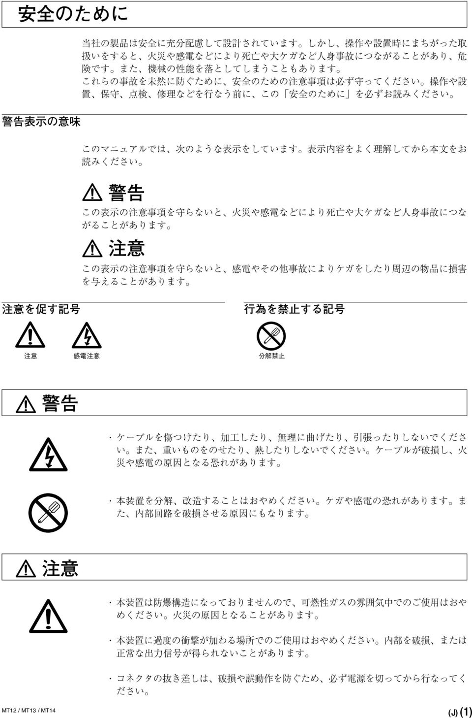
11 Safety Precautions Magnescale Co., Ltd. products are designed in full consideration of safety. However, improper handling during operation or installation is dangerous and may lead to fire, electric shock or other accidents resulting in serious injury or death. In addition, these actions may also worsen machine performance. Therefore, be sure to observe the following safety precautions in order to prevent these types of accidents, and to read these "Safety Precautions" before operating, installing, maintaining, inspecting, repairing or otherwise working on this unit. Warning Indication Meanings The following indications are used throughout this manual, and their contents should be understood before reading the text. Warning Failure to observe these precautions may lead to fire, electric shock or other accidents resulting in serious injury or death. Caution Failure to observe these precautions may lead to electric shock or other accidents resulting in injury or damage to surrounding objects. Symbols requiring attention Symbols prohibiting actions CAUTION ELECTRICAL SHOCK DO NOT DISASSEMBLE Warning Do not damage, modify, excessively bend, pull on, place heavy objects on or heat the cable, as this may damage the cable and result in fire or electric shock. Do not disassemble or modify the unit, as this may result in injury or electric shock. These actions may also damage the internal circuitry. Caution The unit does not have an explosion-proof structure. Therefore, do not use the unit in an atmosphere charged with inflammable gases as this may result in fire. Do not use the unit in places where it may receive excessive shocks. Otherwise the inside of the unit may be damaged or the unit may become unable to produce normal output signals. Be sure to turn off the power before connecting or disconnecting connectors in oder to prevent damage or misoperation. (E) (1)

12 General precautions When using Magnescale Co., Ltd. products, observe the following general precautions along with those given specifically in this manual to ensure proper use of the products. Before and during operations, be sure to check that our products function properly. Provide adequate safety measures to prevent damages in case our products should develop malfunctions. Use outside indicated specifications or purposes and modification of our products will void any warranty of the functions and performance as specified of our products. When using our products in combination with other equipment, the functions and performances as noted in this manual may not be attained, depending on operating and environmental conditions. (2) (E)

13 Operating Cautions Do not route the connecting cable through the same duct as the machine power line. Take preventive steps when the noises from other equipment may disturb the power supply line to the units. When providing DC power, be sure to use within the specified voltage range. Do not pull the cable forcibly or pull at the cable when you connect or disconnect it. Such handling may cause a break in the line. Be sure to ground the measuring unit s frame to prevent misoperation due to noise or static electricity. For installation of the interpolator, avoid a location exposed to chips, cutting oil, or machine oil. If unavoidable, take adequate countermeasures. The ambient temperature should be in the range of 0 ºC to 50 ºC (32 ºF to 122 ºF). Avoid exposure to direct sunlight, hot air currents, or heated air. (E) 1

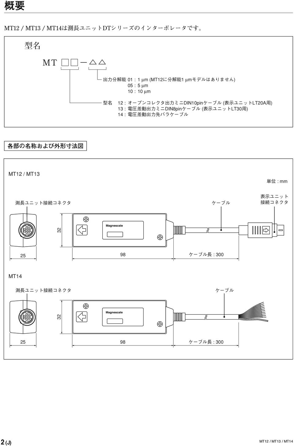
14 Outline MT12, MT13, and MT14 are interpolators for use with the DT series measuring unit. Model MT Output resolution 01 : 1 µm (The 1 µm resolution model is not available in the MT12.) 05 : 5 µm 10 : 10 µm Model 12 : Open collector output mini-din 10-pin cable (for LT20A counter unit) 13 : Voltage differential output mini-din 8-pin cable (for LT30 counter unit) 14 : Voltage differential output open-end cable Parts name and Dimensions MT12 / MT13 Measuring unit connector Cable Unit : mm/inch Counter unit connector 32/1.26" 25/0.98" 98/3.86" Cable length : 300/11.81" MT14 Measuring unit connector Cable 32/1.26" 25/0.98" 98/3.86" Cable length : 300/11.81" 2 (E)
 14 : Voltage differential output open-end cable Parts name and Dimensions MT12 / MT13 Measuring unit connector Cable Unit : mm/inch Counter unit")
15 L Specifications Model MT12-05/10 MT13-01/05/10 MT14-01/05/10 Compatible measuring units Maximum response speed DT512/DT12/DT m/min Power voltage DC5 V ±4 % Power consumption 0.9 W 1.2 W (when output load of 120Ω is connected) Output format NPN open collector Voltage differential line driver Operating temperature and humidity range Storage temperature and humidity range Dimensions Mass 0 to +50 ºC (no condensation) 10 to +60 ºC (20 to 90 %RH) See the Dimensional Diagram. About 90 g Specifications and appearances of the products are subject to change without notice because of improvement. L Phase difference for A/B phase output Changes as follows according to the traveling velocity of the measuring unit. Model MTMM-01 MTMM-05 MTMM-10 Output phase difference (µs) Velocity : 0 < v < v < v v (m/min) 2.5 < v < v < v < v < v < v (100) 5 12 < v < v (100) < v < v (100) 0.5 An alarm is output at a traveling velocity of 100 to 115 m/min. The sampling frequency of the output signal is 120 µs. L Alarm signal This signal is output when the response acceleration is exceeded or when a measuring unit is not connected. The minimum output pulse width is 10 ms, and the alarm output signal also recovers automatically when the alarm status is canceled. L Cable extension The CE08 extension cable (optional accessory) can be used to extend the cable length between the measuring unit and interpolator. Use a cable that is 15 m or less in length between the interpolator and measuring unit. 15 m or less DT512/DT12/DT32 Interpolator MT12/MT13/MT14 (E) 3

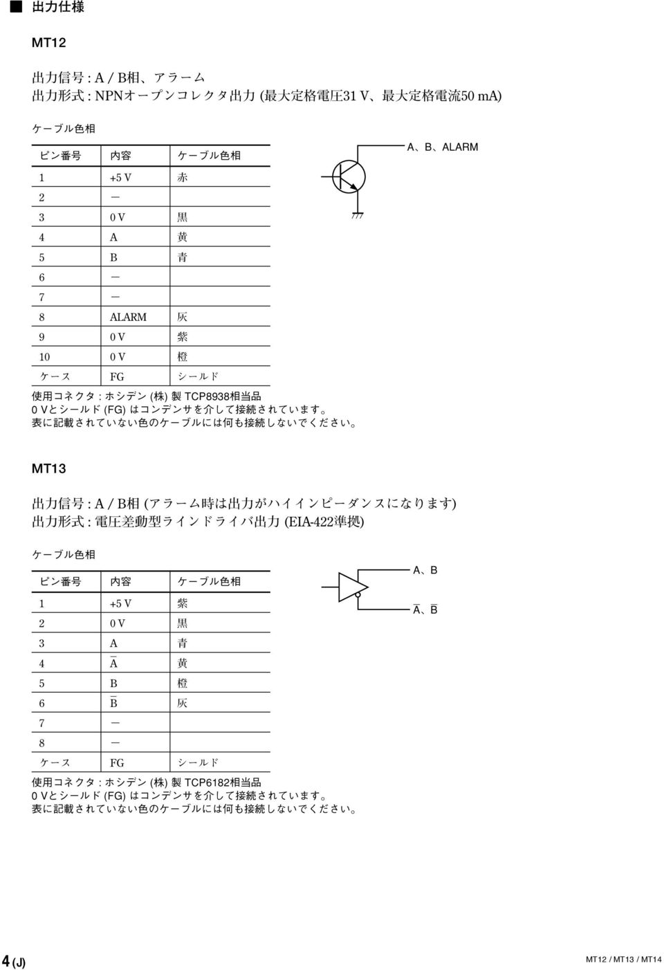
16 L Output specifications MT12 Output signal : A/B phase, Alarm Output format : NPN open collector output (maximum rated voltage: 31 V, maximum rated current: 50 ma) Cable color Pin no. Description Cable color A, B, ALARM 1 +5 V Red V Black 4 A Yellow 5 B Blue ALARM Gray 9 0 V Purple 10 0 V Orange Case FG Shield Connector used: Hosiden TCP8938 or equivalent product 0V and the shield (FG) are connected with a capacitor. Nothing should be connected to cables with colors not found in this table. MT13 Output signal : A/B phase (The output becomes high impedance during an alarm.) Output format : Voltage differential line driver output (compliant with EIA-422) Cable color Pin no. Description Cable color 1 +5 V Purple 2 0 V Black 3 A Blue 4 A Yellow 5 B Orange 6 B Gray 7 8 Case FG Shield Connector used: Hosiden TCP6182 or equivalent product 0V and the shield (FG) are connected with a capacitor. Nothing should be connected to cables with colors not found in this table. A, B A, B 4 (E)
 Output format : Voltage differential line driver output (compliant with EIA-422) Cable color Pin no.")
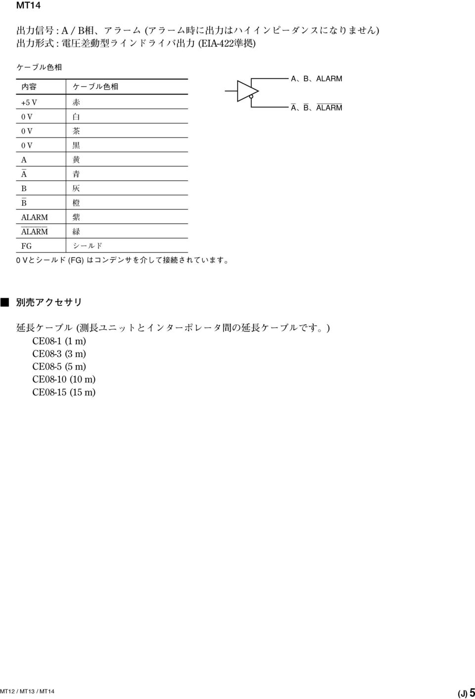
17 MT14 Output signal : A/B phase, Alarm (The output does not become high impedance during an alarm.) Output format : Voltage differential line driver output (compliant with EIA-422) Cable color Description Cable color A, B, ALARM +5 V Red 0 V White 0 V Brown 0 V Black A Yellow A Blue B Gray B Orange ALARM Purple ALARM Green FG Shield 0V and the shield (FG) are connected with a capacitor. A, B, ALARM L Optional Accessories Extension cable (These are extension cables for use between measuring unit and the interpolator.) CE08-1 (1 m) CE08-3 (3 m) CE08-5 (5 m) CE08-10 (10 m) CE08-15 (15 m) (E) 5

18 6 (E)

19 Sicherheitsmaßnahmen Bei dem Entwurf von Magnescale Co., Ltd. Produkten wird größter Wert auf die Sicherheit gelegt. Unsachgemäße Handhabung während des Betriebs oder der Installation ist jedoch gefährlich und kann zu Feuer, elektrischen Schlägen oder anderen Unfällen führen, die schwere Verletzungen oder Tod zur Folge haben können. Darüber hinaus kann falsche Behandlung die Leistung der Maschine verschlechtern. Beachten Sie daher unbedingt die besonders hervorgehobenen Vorsichtshinweise in dieser Bedienungsanleitung, um derartige Unfälle zu verhüten, und lesen Sie die folgenden Sicherheitsmaßnahmen vor der Inbetriebnahme, Installation, Wartung, Inspektion oder Reparatur dieses Gerätes oder der Durchführung anderer Arbeiten durch. Bedeutung der Warnhinweise Bei der Durchsicht dieses Handbuchs werden Sie auf die folgenden Hinweise und Symbole stoßen. Machen Sie sich mit ihrer Bedeutung vertraut, bevor Sie den Text lesen. Warnung Eine Missachtung dieser Hinweise kann zu Feuer, elektrischen Schlägen oder anderen Unfällen führen, die schwere Verletzungen oder Tod zur Folge haben können. Vorsicht Eine Missachtung dieser Hinweise kann zu elektrischen Schlägen oder anderen Unfällen führen, die Verletzungen oder Sachbeschädigung der umliegenden Objekte zur Folge haben können. Zu beachtende Symbole Symbole, die Handlungen verbieten VORSICHT ELEKTRISCHER SCHLAG NICHT ZERLEGEN Warnung Vorsicht Das Kabel nicht beschädigen, verändern, übermäßig knicken, daran ziehen, schwere Objekte darauf stellen oder es erwärmen, da es hierdurch beschädigt und ein Feuer oder ein elektrischer Schlag hervorgerufen werden kann. Das Gerät nicht zerlegen oder verändern, da dies zu Verbrennungen oder elektrischen Schlägen führen kann. Durch derartige Maßnahmen können auch die internen Stromkreise beschädigt werden. Das Gerät ist nicht explosionsgeschützt. Es darf daher keinesfalls in einer Umgebung verwendet werden, die brennbare Gase enthält, da hierdurch ein Feuer entstehen könnte. Das Gerät an Stellen nicht verwenden, wo das starken Erschütterungen ausgezetzt sind, da hierdurch das Innere des Geräts beschädigt werden könnte oder das Gerät normale Ausgänge nicht ausgeben könnte. Unbedingt darauf achten, dass die Stromversorgung ausgeschaltet wird, ehe der Steckverbinder abgetrennt werden, damit es nicht zu Schäden oder Fehlfunktionen kommt. (G) (1)

20 Allgemeine Vorsichtsmaßnahmen Beachten Sie bei der Verwendung von Magnescale Co., Ltd. Produkten die folgenden allgemeinen sowie die in dieser Anleitung besonders hervorgehobenen Vorsichtsmaßnahmen, um eine sachgerechte Behandlung der Produkte zu gewährleisten. Vergewissern Sie sich vor und während des Betriebs, dass unsere Produkte einwandfrei funktionieren. Sorgen Sie für geeignete Sicherheitsmaßnahmen, um im Falle von Gerätestörungen Schäden auszuschließen. Wenn das Profukt modifiziert oder nicht seinem Zweck entsprechend verwendet wird, erlischt die Garantie für die angegebenen Funktionen und Leistungsmerkmale. Bei Verwendung unserer Produkte zusammen mit Geräten anderer Hersteller werden je nach den Umgebungsbedingungen die in der Anleitung beschriebenen Funktionen und Leistungsmerkmale möglicherweise nicht erreicht. (2) (G)

21 Zur besonderen Beachtung Anschlusskabel und Netzkabel dürfen nicht zusammen in derselben Durchführung verlegt werden. Um Störungen der Digiruler-Stromzufuhr zu verhindren, sollten auch hier vorbeugende Maßnahmen getroffen werden. Achten Sie bei Gleichstromversorgung darauf, dass die Spannung innerhalb des vorgeschriebenen Bereiches liegt. Nicht mit Gewalt am Kabel ziehen; beim Anschließen und Abklemmen nicht am Kabel ziehen bzw. drücken, da sonst das Kabel beschädigt wird. Der Rahmen der Messsonde sollte unbedingt geerdet werden, um durch Rauschen oder statische Elektrizität verursachten Fehlbetrieb zu vermeiden. Bei der Installation der Anzeigeeinheit Aufstellorte meiden, an denen sie Spänen, Schneidöl oder Maschinenöl Ausgesetzt ist. Ist dies nicht vermeidbar, entsprechende Gegenmaßnahmen ergreifen. Die Umgebungstemperature muss im Bereich zwischen 0 und +50 ºC liegen. Direkte Sonneneinstrahlung, Warm- und Heissluft vermeiden. (G) 1
22 Umriss MT12, MT13 und MT14 sind Interpolatoren für den Einsatz mit der Messstabseinheit der Serie DT. Modell MT Ausgabeauflösung 01 : 1 µm (Das Modell mit 1 µm Auflösung ist für MT12 nicht erhältlich.) 05 : 5 µm 10 : 10 µm Modell 12 : 10-poliges Mini-DIN-Kabel, Open-Collector-Ausgabe (für Zählereinheit LT20A) 13 : 8-poliges Mini-DIN-Kabel, Spannungsdifferentialausgabe (für Anzeigeeinheit LT30) 14 : Open-End-Kabel, Spannungsdifferentialausgabe Teilebezeichnungen und Abmessungen MT12 / MT13 Messstabseinheit-Steckverbinder Kabel Einheit: mm Anzeigeeinheit- Steckverbinder Kabellänge : 300 MT14 Messstabseinheit-Steckverbinder Kabel Kabellänge : (G)
23 L Technische Daten Modell MT12-05/10 MT13-01/05/10 MT14-01/05/10 Kompatible Messstabseinheiten Maximale Ansprechgeschwindigkeit DT512/DT12/DT m/min Versorgungsspannung DC 5 V ±4 % Leistungsaufnahme 0,9 W 1,2 W (bei Anschluss einer Ausgangsbelastung von 120 Ω) Ausgabeformat NPN-Open-Collector Spannungsdifferential-Leitungstreiber Betriebstemperatur- und 0 bis 50 ºC (keine Kondensation) -luftfeuchtigkeitsbereich Lagertemperatur- und 10 bis 60 ºC (20 bis 90 % RH) -luftfeuchtigkeitsbereich Abmessungen Siehe die Abmessungen. Masse ca. 90 g Änderungen der technischen Daten und Ausführungen vorbehalten. L Phasendifferenz für A/B-Phasenausgabe Ändert sich wie folgt gemäß der Verfahrgeschwindigkeit der Messstabseinheit. Modell MTMM-01 MTMM-05 MTMM-10 Ausgangsphasendifferenz (µs) Geschwindigkeit : 0 < v 2,5 0 < v 12,5 0 < v v (m/min) 2,5 < v 6,25 12,5 < v 31,25 25 < v 62,5 8 6,25 < v 12 31,25 < v 60 62,5 < v (100) 5 12 < v < v (100) 2,5 24 < v < v (100) 0,5 Ein Alarm wird bei einer Verfahrgeschwindigkeit von 100 bis 115 m/min ausgegeben. Die Abtastfrequenz des Ausgangssignals beträgt 120 µs. L Alarm signal Dieses Signal wird ausgegeben, wenn die Ansprechbeschleunigung überschritten wird, oder wenn keine Messstabseinheit angeschlossen ist. Die minimale Ausgangsimpulsbreite beträgt 10 ms, und das Alarmausgabesignal wird bei Aufhebung des Alarmzustands ebenfalls automatisch zurückgestellt. L Kabelverlängerung Das Verlängerungskabel CE08 (Option) kann zur Verlängerung der Kabellänge zwischen Messstabseinheit und Interpolator verwendet werden. Verwenden Sie ein Kabel von maximal 15 m Länge zwischen Interpolator und Messstabseinheit. maximal 15 m DT512/DT12/DT32 Interpolator MT12/MT13/MT14 (G) 3
24 L Ausgangsspezifikationen MT12 Ausgangssignal : A/B-Phase, Alarm Ausgabeformat : NPN Open-Collector-Ausgabe (maximale Nennspannung: 31 V, maximale Nennstromstärke: 50 ma) Kabelfarbe Stift-Nr. Beschreibung Kabelfarbe A, B, ALARM 1 +5 V Rot V Schwarz 4 A Gelb 5 B Blau ALARM Grau 9 0 V Violett 10 0 V Orange Gehäuse FG Abgeschirmt Verwendeter Steckverbinder: Hosiden TCP8938 oder gleichwertiges Produkt 0 V und das Abschirmblech (FG) sind mit einem Kondensator verbunden. An Kabel, deren Farbe nicht in dieser Tabelle aufgeführt ist, sollte nichts verbunden werden. MT13 Ausgangssignal : A/B-Phase (Der Ausgang erhält während eines Alarms hohe Impedanz.) Ausgabeformat : Spannungsdifferential-Leitungstreiberausgabe (entspricht EIA-422) Kabelfarbe Stift-Nr. Beschreibung Kabelfarbe A, B 1 +5 V Violett 2 0 V Schwarz 3 A Blau 4 A Gelb 5 B Orange 6 B Grau 7 8 Gehäuse FG Abgeschirmt A, B Verwendeter Steckverbinder: Hosiden TCP6182 oder gleichwertiges Produkt 0 V und das Abschirmblech (FG) sind mit einem Kondensator verbunden. An Kabel, deren Farbe nicht in dieser Tabelle aufgeführt ist, sollte nichts verbunden werden. 4 (G)
25 MT14 Ausgangssignal : A/B-Phase, Alarm (Der Ausgang erhält während eines Alarms keine hohe Impedanz.) Ausgabeformat : Spannungsdifferential-Leitungstreiberausgabe (entspricht EIA-422) Kabelfarbe Beschreibung Kabelfarbe A, B, ALARM +5 V Rot 0 V Weiß 0 V Braun 0 V Schwarz A Gelb A Blau B Grau B Orange ALARM Violett ALARM Grün FG Abgeschirmt 0 V und das Abschirmblech (FG) sind mit einem Kondensator verbunden. A, B, ALARM L Option Verlängerungskabel (Dies sind Verlängerungskabel für den Gebrauch zwischen Messstabseinheit und Interpolator.) CE08-1 (1 m) CE08-3 (3 m) CE08-5 (5 m) CE08-10 (10 m) CE08-15 (15 m) (G) 5
26 The material contained in this manual consists of information that is the property of Magnescale Co., Ltd. and is intended solely for use by the purchasers of the equipment described in this manual. Magnescale Co., Ltd. expressly prohibits the duplication of any portion of this manual or the use thereof for any purpose other than the operation or maintenance of the equipment described in this manual without the express written permission of Magnescale Co., Ltd. Le matériel contenu dans ce manuel consiste en informations qui sont la propriété de Magnescale Co., Ltd. et sont destinées exclusivement à l'usage des acquéreurs de l'équipement décrit dans ce manuel. Magnescale Co., Ltd. interdit formellement la copie de quelque partie que ce soit de ce manuel ou son emploi pour tout autre but que des opérations ou entretiens de l'équipement à moins d'une permission écrite de Magnescale Co., Ltd. Die in dieser Anleitung enthaltenen Informationen sind Eigentum von Magnescale Co., Ltd. und sind ausschließlich für den Gebrauch durch den Käufer der in dieser Anleitung beschriebenen Ausrüstung bestimmt. Magnescale Co., Ltd. untersagt ausdrücklich die Vervielfältigung jeglicher Teile dieser Anleitung oder den Gebrauch derselben für irgendeinen anderen Zweck als die Bedienung oder Wartung der in dieser Anleitung beschriebenen Ausrüstung ohne ausdrückliche schriftliche Erlaubnis von Magnescale Co., Ltd.
27 z x q w q w e r t c v b
28 Shinagawa Intercity Tower A-18F, , Konan, Minato-ku, Tokyo , Japan Printed in Japan 2008 Magnescale Co., Ltd.
BL57-NE
 (J) (1) 1 CLASS 1 LASER PRODUCT CLASS 1 LASER PRODUCT LASERSCHUTZKLASSE 1 PRODUKT TO EN 60825 (2) (J) (J) (3) C (4) (J) (J) (5) [For U.S.A. and Canada] THIS CLASS A DIGITAL DEVICE COMPLIES WITH PART15
MIDI_IO.book
 MIDI I/O t Copyright This guide is copyrighted 2002 by Digidesign, a division of Avid Technology, Inc. (hereafter Digidesign ), with all rights reserved. Under copyright laws, this guide may not be duplicated
WARNING To reduce the risk of fire or electric shock,do not expose this apparatus to rain or moisture. To avoid electrical shock, do not open the cabi
 ES-600P Operating Instructions WARNING To reduce the risk of fire or electric shock,do not expose this apparatus to rain or moisture. To avoid electrical shock, do not open the cabinet. Refer servicing
Tab 5, 11 Tab 4, 10, Tab 3, 9, 15Tab 2, 8, 14 Tab 1, 7, 13 2
 COMPANION 20 MULTIMEDIA SPEAKER SYSTEM Owner s Guide Tab 5, 11 Tab 4, 10, Tab 3, 9, 15Tab 2, 8, 14 Tab 1, 7, 13 2 Tab1, 7, 13 Tab 2, 8, 14 Tab 3, 9, 15 Tab 4, 10, Tab 5, 11 This product conforms to all
*C3200−îŒ{fiI‡È”g‡¢Łû01-07
 2 2 1 2 3 4 a b c d 5 6 7 8 9 10 11 12 13 14 2 2 15 16 I/O ipk 17 18 19 20 LAN! 21 22 23 24 25 26 Web Navi Text To Speech 27 Outlook Intellisync HancomMobileWord/Sheet HancomMobileWord/Sheet 28 29 30 a
ユーザーガイド
 SWR12 ...4...4...4...5...5... 5... 5... 5...6...7... 7 LED... 7... 7... 8... 8... 9... 9 SmartBand 2 Android...10... 10... 10... 11 LED... 12... 12... 13... 13... 13 Google Fit... 13 STAMINA... 14 STAMINA...
内蔵ハードディスクユニット-20GB (PG-HD2E4H) 内蔵ハードディスクユニット-40GB (PG-HD4E4H)取扱説明書 HARD DISK DRIVE 20GB(PG-HD2E4H) HARD DISK DRIVE 40GB(PG-HD4E4H) USER'S GUIDE
 内蔵ハードディスクユニット-40GB (PG-HD4E4H)取扱説明書 HARD DISK DRIVE 20GB(PG-HD2E4H) HARD DISK DRIVE 40GB(PG-HD4E4H) USER'S GUIDE") B7FY-0351-02 J E J 1 J 1 2 3 2 4 J 3 4 Preface Thank you very much for purchasing the hard disk drive. This hard disk drive provides a IDE interface and can be installed in the 3.5-inch storage bay of
B7FY-0351-02 J E J 1 J 1 2 3 2 4 J 3 4 Preface Thank you very much for purchasing the hard disk drive. This hard disk drive provides a IDE interface and can be installed in the 3.5-inch storage bay of
- 1 -
 - 1 - - 2 - - 3 - - 4 - - 5 - - 6 - - 7 - - 8 - - 9 - - 10 - - 11 - - 12 - - 13 - - 14 - - 15 - 1 2 1-16 - 2 3 4 5 6 7-17 - 1 2 1 2 3 4-18 - 1 2 3 4 1 2-19 - 1 2 3 1 2-20 - 3 4 5 6 7 1-21 - 1 2 3 4-22
ユーザーガイド
 BKC52 ...3... 3...4... 4... 4... 5...6... 6... 6... 7... 7...8 Legal information...9 Declaration of Conformity for BKC52... 9 2 Xperia TM Z2 Tablet Xperia TM Z2 Tablet NFC LED Bluetooth LED microusb E
ユーザーガイド
 SWR30 ...3... 3... 3... 4... 4... 5... 5... 5... 6... 6 SmartBand Talk...7 SmartBand Talk... 7 SmartBand Talk... 8... 8 Android... 9... 9... 10... 10... 11... 11... 11 SmartBand... 12... 12... 12... 13
ユーザーガイド
 BSP60 ...3...4 本機の使用場所について... 4 本機の取り扱いについて... 4 お手入れ... 4...5...6 ディスプレイ... 6...7...8...8 電源をオンする... 8 電源をオフする... 8...8 NFC 機能をお使いになる場合... 8 NFC 機能をお使いにならない場合... 9 NFC...10...10 本機をリセットする... 10 本機を初期設定に戻す...
DZ-GX20/DZ-MV780取扱説明書(上巻)
") DZ-GX20 DZ-MV780(S) DZ-MV780(R) DZ-MV780(A) Important Information WARNING : To prevent fire or shock hazard, do not expose this unit to rain or moisture. WARNING : To prevent fire or shock hazard, use
DZ-GX20 DZ-MV780(S) DZ-MV780(R) DZ-MV780(A) Important Information WARNING : To prevent fire or shock hazard, do not expose this unit to rain or moisture. WARNING : To prevent fire or shock hazard, use
PC_14ZY6_BFT150A_US_ indd
 PARTS CATALOG BFT 0A OB NO.00-ZY- US Instruction for use of parts catalogue This parts catalogue was prepared based on the latest information available as of October,. See the Service Bulletin for any
LED...5 LED... 5 LED... 5 LED Xperia Ear Duo... 7 Xperia Ear Duo Xperia Ear Duo
 XEA20 ...3...3... 3... 4 LED...5 LED... 5 LED... 5 LED... 5...6... 6... 7 Xperia Ear Duo... 7 Xperia Ear Duo... 9... 10 Xperia Ear Duo...12... 12... 13... 14... 15... 15 Assistant for Xperia TM... 15 Clova...
: (20ºC +/- 5ºC) : : 3 : : RV Bose Corporation hereby declares that this product is in compliance with the essential requirements and other relevant p
 : : 3 : : RV Bose Corporation hereby declares that this product is in compliance with the essential requirements and other relevant p") Bose SoundLink Mini Bluetooth speaker II : (20ºC +/- 5ºC) : : 3 : : RV Bose Corporation hereby declares that this product is in compliance with the essential requirements and other relevant provisions
Bose SoundLink Mini Bluetooth speaker II : (20ºC +/- 5ºC) : : 3 : : RV Bose Corporation hereby declares that this product is in compliance with the essential requirements and other relevant provisions
DZ-HS503 取扱説明書
 DZ-HS503 Important Information WARNING : To prevent fire or shock hazard, do not expose this unit to rain or moisture. WARNING : To prevent fire or shock hazard, use the recommended accessories only. CAUTION
WIF6002-e
 Installation and Operating Instructions Sartorius IF.. Standard and IF...CE Verifiable Models Flat-bed Scale 98648-012-37 2 ! 3 4 5 6 7 General View of the Equipment 2 4 1 3 5 6 1 Weighing platform 2 Handles
DZ-GX3300/GX3100/GX3100取扱説明書
 DZ-GX3300(S)/(B) DZ-GX3200 DZ-GX3100 Important Information WARNING : To prevent fire or shock hazard, do not expose this unit to rain or moisture. WARNING : To prevent fire or shock hazard, use the recommended
DZ-HS303 取扱説明書
 DZ-HS303(S)/(A) Important Information WARNING : To prevent fire or shock hazard, do not expose this unit to rain or moisture. WARNING : To prevent fire or shock hazard, use the recommended accessories
080906_…o…−…^…b…vVSCW
 Thyristor Type Single-Phase Power Regulator 2030 A 6A 150200A TOKYO RIKOSHA CO., LTD Latest VARITAP VSCW Series Achieved 1/2 the width (our company comparison). Free Power source of 100 to 240V specification.cover-type
Specification for Manual Pulse Generator, GFK-2262
 Specification change in Manual Pulse Generator () A) Abstract This document explains about the specification change in Manual Pulse Generator (). The production of the former specifications written in
 FCC This product is conform to the FCC standards. FCC Rules (Federal Communications Commission) This product complies with Part15 Subpart B and C of the FCC Rules. FCC ID : MK4TR3XM-SX01 FCC NOTICE This
Spark Mini Booster - Japanese Manual Version 1.0-1 EMC/EMI 2 3 4 5 6 1. 6 2. 6 3. 6 4. LEVEL - 6 5. 6 PrimeTime 6 7 11 FAQ 11 12 12 a
 Spark Mini Booster Spark Mini Booster - Japanese Manual Version 1.0-1 EMC/EMI 2 3 4 5 6 1. 6 2. 6 3. 6 4. LEVEL - 6 5. 6 PrimeTime 6 7 11 FAQ 11 12 12 a - - 1) 2) 3) 4) 5) 6) 7) 8) 9) 10) 11) 12) 13) 14)
FreeSpace.book
 IZA 190-HZ IZA 250-LZ ZA 190-HZ ZA 250-LZ FreeSpace Integrated Zone Amplifier/Zone Amplifier * 1. 2. 3. 4. 5. 6. 7. 8. 9. 2 2 10. 11. 12. 13. 14. 15. 16. 17. 40 C This product conforms to all EU Directive
 0 PARTS CATALOG BFT A BFT 0A OB NO.00-ZYET- US Instruction for use of parts catalogue This parts catalogue was prepared based on the latest information available as of October, 0. See the Service Bulletin
DG805BL/DG810B/DG810BL
 / Digital Gauge / Digitale Meßsonde DG805BL / DG810B / DG810BL Read all the instructions in the manual carefully before use and strictly follow them. Keep the manual for future references. Lesen Sie die
VIRTUALLY INVISIBLE 300 WIRELESS SURROUND SPEAKERS
 VIRTUALLY INVISIBLE 300 WIRELESS SURROUND SPEAKERS 1. 2. 3. 4. 5. 6. 7. 8. ( ) 9. 10. 11. 12. 2000m 2 - This device complies with part 15 of the FCC Rules and with Industry Canada license-exempt RSS standard(s).
Huawei G6-L22 QSG-V100R001_02
 G6 1 2 3 4 5 6 7 8 9 10 11 12 13 14 15 16 1 2 3 17 4 5 18 UI 100% 8:08 19 100% 8:08 20 100% 8:08 21 100% 8:08 22 100% 8:08 ********** 23 100% 8:08 Happy birthday! 24 S S 25 100% 8:08 26 http://consumer.huawei.com/jp/
P3FY J E
 P3FY-1490-01 J E J 1 J 1 2 2 J 3 3 4 4 5 J 5 Preface Thank you very much for purchasing the hard disk drive. This hard disk drive provides a IDE interface and can be installed in the 3.5-inch storage
DG110B
 / Digital Gauge / Digitale Meßtaster DG110B Read all the instructions in the manual carefully before use and strictly follow them. Keep the manual for future references. Lesen Sie die ganze Anleitung vor
音響部品アクセサリ本文(AC06)PDF (Page 16)
PDF (Page 16)") Guide for Electret Condenser Microphones A microphone as an audio-electric converting device, whose audio pickup section has a structure of a condenser consisting of a diaphragm and a back plate opposite
Guide for Electret Condenser Microphones A microphone as an audio-electric converting device, whose audio pickup section has a structure of a condenser consisting of a diaphragm and a back plate opposite
クイックスタートガイド [SC-06D]
![クイックスタートガイド [SC-06D]](/thumbs/96/127590204.jpg "クイックスタートガイド [SC-06D]") SC-06D a g h a i b j c k m n o p q s t u v w d e f l r g a b c d e f g h i j k l m n o p q r s t u v w x x a ab c 3 1 2 b c d a b 1 2 e a ab c 3 1 2 b c d e f a b c d e f a b
SC-06D a g h a i b j c k m n o p q s t u v w d e f l r g a b c d e f g h i j k l m n o p q r s t u v w x x a ab c 3 1 2 b c d a b 1 2 e a ab c 3 1 2 b c d e f a b c d e f a b
 (1) Precautions in selecting valve type 1) 2) WARNING Use the valve at maximum operating pressure or below. CAUTION Use general mineral oil series hydraulic oil. The valve model No. described in this catalogue
i5 Catalyst Case Instructions JP
 Catalyst iphone iphone iphone ON/OFF O O Touch ID Page 01 iphone O O O O O Page 02 ( ) O OK O O O 30 30 min Page 03 ( ) 30 O iphone iphone iphone iphone iphone iphoneiphone Catalyst ON/OFF iphone iphone
<3035EA8E93A18CF695E32E696E6464>
 Deutsch-Unterricht mit YouTube SAITO Kosuke Im Unterricht arbeite ich mit dem Internet-Videoportal YouTube. Ich nutze dieses Videoportal für Aussprachübungen und-prüfungen. Dieser Bericht beschäftigt sich
クイックスタートガイド [SC-03E]
![クイックスタートガイド [SC-03E]](/thumbs/96/127590290.jpg "クイックスタートガイド [SC-03E]") a L R 2.4 FH1 / DS4 / OF4 / XX8 IEEE802.11b/g/n IEEE802.11a/n J52 W52 W53 W56 g h a i b j c k m n o p q s t u v w t d e f l g a b c d r e f g h i j k l m n o p q r s t u v w x
a L R 2.4 FH1 / DS4 / OF4 / XX8 IEEE802.11b/g/n IEEE802.11a/n J52 W52 W53 W56 g h a i b j c k m n o p q s t u v w t d e f l g a b c d r e f g h i j k l m n o p q r s t u v w x
 / Scale Unit/ Skaleneinheit Read all the instructions in the manual carefully before use and strictly follow them. Keep the manual for future references. Lesen Sie die ganze Anleitung vor dem Betrieb aufmerksam
OPERATING INSTRUCTION RNTD Model NTD Model To the use r In order to use the torque driver properly and safely,please read the instructions before oper
 OPERATING INSTRUCTION RNTD Model NTD Model To the use r In order to use the torque driver properly and safely,please read the instructions before operation.if there are any questions,please contact a Tohnichi
Mitsubishi FR-BAL Manual
 ANIOIZED INVEE Instruction Manual AC POWE FACO IMPOVING AC EACO F-BAL hank you for choosing the Mitsubishi transistorized inverter option. his instruction manual gives handling information and precautions
MLA8取扱説明書
 (5)-2 2 (5)-2 3 (5)-2 4 5 2 3 4 5 6 7 1 2 3 4 5 6 7 8 POWER ON / OFF 1 1 n 2 3 4 5 6 7 n 6 AC IN 8 MODEL MAL8 MADE IN INDONESIA 7 6 5 4 OUTPUT +4dBu ANALOG OUTPUT +4dBu G G 3 2 1 8 7 6 5 INPUT 4 3 2 1
AIC128-D Getting Started
 DANTE ACCELERATOR AUDIO INTERFACE CARD AIC128-D Italiano Deutsch English Français Español Getting Started Einführung Prise en Main Cómo Empezar Guida Introduttiva Приступая к работе 入门 EN DE FR ES IT RU
How to read the marks and remarks used in this parts book. Section 1 : Explanation of Code Use In MRK Column OO : Interchangeable between the new part
 Reservdelskatalog MIKASA MVB-85 rullvibrator EPOX Maskin AB Postadress Besöksadress Telefon Fax e-post Hemsida Version Box 6060 Landsvägen 1 08-754 71 60 08-754 81 00 info@epox.se www.epox.se 1,0 192 06
How to read the marks and remarks used in this parts book. Section 1 : Explanation of Code Use In MRK Column OO : Interchangeable between the new part
 Reservdelskatalog MIKASA MT65H vibratorstamp EPOX Maskin AB Postadress Besöksadress Telefon Fax e-post Hemsida Version Box 6060 Landsvägen 1 08-754 71 60 08-754 81 00 info@epox.se www.epox.se 1,0 192 06
How to read the marks and remarks used in this parts book. Section 1 : Explanation of Code Use In MRK Column OO : Interchangeable between the new part
 Reservdelskatalog MIKASA MVC-50 vibratorplatta EPOX Maskin AB Postadress Besöksadress Telefon Fax e-post Hemsida Version Box 6060 Landsvägen 1 08-754 71 60 08-754 81 00 info@epox.se www.epox.se 1,0 192
IEC :2014 (ed. 4) の概要 (ed. 2)
 の概要 (ed. 2)") IEC 60601-1-2:2014 (ed. 4) (ed. 2) e 2018 4 2 1 1 2 / 1 2.1............... 2 2.2............... 3 2.3.................. 4 3 6 4 6 4.1.................. 6 4.1.1............... 7 4.1.2....... 7 4.1.3............
IEC 60601-1-2:2014 (ed. 4) (ed. 2) e 2018 4 2 1 1 2 / 1 2.1............... 2 2.2............... 3 2.3.................. 4 3 6 4 6 4.1.................. 6 4.1.1............... 7 4.1.2....... 7 4.1.3............
How to read the marks and remarks used in this parts book. Section 1 : Explanation of Code Use In MRK Column OO : Interchangeable between the new part
 Reservdelskatalog MIKASA MCD-L14 asfalt- och betongsåg EPOX Maskin AB Postadress Besöksadress Telefon Fax e-post Hemsida Version Box 6060 Landsvägen 1 08-754 71 60 08-754 81 00 info@epox.se www.epox.se
Rangänderung bei Teilhypotheken Wird die Forderung geteilt, so ist zur Änderung des Rangverhältnisses der Teilhypotheken untereinander die Zustimmung
 Rangänderung bei Teilhypotheken Wird die Forderung geteilt, so ist zur Änderung des Rangverhältnisses der Teilhypotheken untereinander die Zustimmung des Eigentümers nicht erforderlich. BGB BGB 175 BGB
2 3
 * This device can only be used inside Japan in areas that are covered by subscription cable TV services. Because of differences in broadcast formats and power supply voltages, it cannot be used in overseas
Options Unit : mm Finger guards Color Model Surface treatment Nickel-chrome plating silver DC Fan 4mm Air Flo
 DC Fan 4mm sq. San Ace 4 1mm thick, 15mm thick (GA type), 15mm thick, 2mm thick (GA type), 2mm thick 28mm thick (GA type), 28mm thick (GE type) 28mm thick (GV type), 28mm thick General Specifications Material
 Hello from the Tone Farm Risk of Electric Shock. Do Not Open. No user serviceable parts inside. Replace fuse with same type/rating only. Do not expose to rain or moisture. CAUTION: WARNING: 0123456789ABCDEF
 5 11 3 1....1 2. 5...4 (1)...5...6...7...17...22 (2)...70...71...72...77...82 (3)...85...86...87...92...97 (4)...101...102...103...112...117 (5)...121...122...123...125...128 1. 10 Web Web WG 5 4 5 ²
I N S T R U M E N T A T I O N & E L E C T R I C A L E Q U I P M E N T box number basic type Standard Specification Material of Enclosure Material of F
 01 Flameproof Junction Box Junction Box Series Our junction boxes are designed and manufactured based on the Recommended Practices for Explosion-Protected Electrical Installations in General Industries
 ! " # $ % & ' ( ) +, -. / 0 1 2 3 4 5 6 7 8 9 : ; < = >? @ A B C D E F G H I J K L M N O P Q R S T U V W X Y Z [ ] ^ _ ` a b c d e f h i j k l m n o p q r s t u v w x y z { } ~ This product is
I N S T R U M E N T A T I O N & E L E C T R I C A L E Q U I P M E N T Pressure-resistant gasket type retreat method effective bulk compressibility Fro
 Cable Gland This is the s to use for Cable Wiring in the hazardous location. It is much easier to install and maintenance and modification compared with Conduit Wiring with Sealing Fitting. The Standard
Z7000操作編_本文.indb
 2 8 17 37Z700042Z7000 46Z7000 28 42 52 61 72 87 2 3 12 13 6 7 3 4 11 21 34 61 8 17 4 11 4 53 12 12 10 75 18 12 42 42 13 30 42 42 42 42 10 62 66 44 55 14 25 9 62 65 23 72 23 19 24 42 8 26 8 9 9 4 11 18
MKS-05 "TERRA-Pプラス 日本語訳取扱説明書
 MKS-05 "TERRA-P+" BICT.412129.021 KE Sparing-Vist Center Sparing-Vist Center ECOTEST (+38 032) 242-15-15 (+38 032) 242-20-15 sales@ecotest.ua 18 ( ) 2 1. 3 2. 3 3. 4 4. 4 5. 6 6. 7 7. 11 8. 11 9. 11 10.
ÉXÅ[ÉpÅ[ÉRÉuÉâï\éÜ
 class SCLE HELICOPTER SUPERCOR W-1W ODY KIT INSTRUCTION MNUL SUPERCOR Please read this manual in its entirety before attempting to assemble the helicopter. This manual explains the parts exclusive to SUPERCOR.
untitled
 DC Fan 8mm sq. General Specifications San Ace 8 15mm thick (GA type), 15mm thick, 2mm thick (GA type) 2mm thick, 25mm thick (GA type), 25mm thick (S type) 25mm thick (GV type), 25mm thick 25mm thick (San
ScanFront300/300P セットアップガイド
 libtiff Copyright (c) 1988-1996 Sam Leffler Copyright (c) 1991-1996 Silicon Graphics, Inc. Permission to use, copy, modify, distribute, and sell this software and its documentation for any purpose is hereby
Air Flow - Static Pressure Characteristics PWM Duty Cycle % 1% 5% CRA312P4K
 Counter Rotating Fan 38mm sq. San Ace 38 48mm thick (CRA type) General Specifications Material Frame: Plastics (Flammability: UL94V-), Impeller: Plastics (Flammability: UL94V-1) Expected Life Refer to
AD8212: 高電圧の電流シャント・モニタ
 7 V typ 7 0 V MSOP : 40 V+ V SENSE DC/DC BIAS CIRCUIT CURRENT COMPENSATION I OUT COM BIAS ALPHA 094-00 V PNP 0 7 V typ PNP PNP REV. A REVISION 007 Analog Devices, Inc. All rights reserved. 0-9 -- 0 40
ÉgÉEÉRÉuÉâï\éÜ
 60 class SCLE HELICOPTER TOWCOR H-1SIII ODY KIT INSTRUCTION MNUL TOWCOR 60 Please read this manual in its entirety before attempting to assemble the helicopter. This manual explains the parts exclusive
2 3 12 13 6 7
 2 8 17 42ZH700046ZH700052ZH7000 28 43 54 63 74 89 2 3 12 13 6 7 3 4 11 21 34 63 65 8 17 4 11 4 55 12 12 10 77 56 12 43 43 13 30 43 43 43 43 10 45 14 25 9 23 74 23 19 24 43 8 26 8 9 9 4 8 30 42 82 18 43
How to read the marks and remarks used in this parts book. Section 1 : Explanation of Code Use In MRK Column OO : Interchangeable between the new part
 Reservdelskatalog MIKASA MVC-88 vibratorplatta EPOX Maskin AB Postadress Besöksadress Telefon Fax e-post Hemsida Version Box 6060 Landsvägen 1 08-754 71 60 08-754 81 00 info@epox.se www.epox.se 1,0 192
*Ł\”ƒ‚ä(DCH800)
") B B B B B B B B B C * This device can only be used inside Japan in areas that are covered by subscription cable TV services. Because of differences in broadcast formats and power supply voltages, it cannot
B B B B B B B B B C * This device can only be used inside Japan in areas that are covered by subscription cable TV services. Because of differences in broadcast formats and power supply voltages, it cannot
H8000操作編
 8 26 35 32H800037H800042H8000 49 55 60 72 2 3 4 48 7 72 32 28 7 8 9 5 7 9 22 43 20 8 8 8 8 73 8 13 7 7 7 55 10 49 49 13 37 49 49 49 49 49 49 12 50 11 76 8 24 26 24 24 6 1 2 3 18 42 72 72 20 26 32 80 34
00_1512_SLIMLINE_BOOK.indb
 PIECE type SLIM type Imbalance value Less interference type, ideal for deep machining Ideal for drilling 2 PIECE REGULAR type Rigidity value Nozzle type When compared to the slim type, it has more rigidity
: Bose SoundLink around-ear Bluetooth headphones : (UL CSA VDE CCC ) Bose Corporation hereby declares that this product is in compliance with
 Bose Corporation hereby declares that this product is in compliance with") Bose SoundLink AROUND-EAR BLUETOOTH HEADPHONES : 3 - - - Bose SoundLink around-ear Bluetooth headphones : (UL CSA VDE CCC ) Bose Corporation hereby declares that this product is in compliance with the
Bose SoundLink AROUND-EAR BLUETOOTH HEADPHONES : 3 - - - Bose SoundLink around-ear Bluetooth headphones : (UL CSA VDE CCC ) Bose Corporation hereby declares that this product is in compliance with the
BS・110度CSデジタルハイビジョンチューナー P-TU1000JS取扱説明書
 C S0 CS Digital Hi-Vision Tuner C C C C S0-0A TQZW99 0 C C C C 4 5 6 7 8 9 C C C C C C C C C C C C C C C C C C C C C C C 0 FGIH C 0 FGIH C C C FGIH FG IH FGIH I H FGIH FGIH 0 C C # $ IH F G 0 # $ # $
Description
 Metal Hybrid Inductor Description Metal Hybrid Inductor Magnetically shielded Suitable for Large Current Size: 4.3 x 4.3 x H2.1 mm Max. Product weight:.18g (Ref.) Halogen Free available Operating temperature
0810_UIT250_soto
 UIT UNIMETER SERIES 250 201 Accumulated UV Meter Digital UV Intensity Meter Research & Development CD Medical Biotech Sterilization Exposure Bonding Manufacturing Curing Production Electronic Components
 0 PARTS CATALOG BFT A BFT 0A OB NO.00-ZYET- EU/EX Instruction for use of parts catalogue This parts catalogue was prepared based on the latest information available as of October, 0. See the Service Bulletin
AN-200A(J-GB).doc :16 AM ページ 2
.doc :16 AM ページ 2") AN-200A(J-GB).doc 10.5.26 11:16 AM ページ 1 JAPANESE VERSION ENGLISH VERSION AN-200A(J-GB).doc 10.5.26 11:16 AM ページ 2 AN-200A(J-GB).doc 10.5.26 11:16 AM ページ 1 S INTRODUCTION Thank you very much for purchasing
AN-200A(J-GB).doc 10.5.26 11:16 AM ページ 1 JAPANESE VERSION ENGLISH VERSION AN-200A(J-GB).doc 10.5.26 11:16 AM ページ 2 AN-200A(J-GB).doc 10.5.26 11:16 AM ページ 1 S INTRODUCTION Thank you very much for purchasing
ES8259取説
 ES8259 B B B B 2 µm µm C C C C µm µm 1 3 4 2 H H 3 C C C C C C C C C C C C C C C C C C C C C C C C C C C 4 B B B B B B B B B B B B 5 B B B C C B B C C B B B C B C B B B 6 7 8 OFF/ON $ & ( $ ' # % # $ %
 6 4 4 9RERE6RE 5 5 6 7 8 9 4 5 6 4 4 5 6 8 4 46 5 7 54 58 60 6 69 7 8 0 9 9 79 0 4 0 0 4 4 60 6 9 4 6 46 5 4 4 5 4 4 7 44 44 6 44 8 44 46 44 44 4 44 0 4 4 5 4 8 6 0 4 0 4 4 5 45 4 5 50 4 58 60 57 54
ScanFront 220/220P 取扱説明書
 libtiff Copyright (c) 1988-1996 Sam Leffler Copyright (c) 1991-1996 Silicon Graphics, Inc. Permission to use, copy, modify, distribute, and sell this software and its documentation for any purpose is hereby
ScanFront 220/220P セットアップガイド
 libtiff Copyright (c) 1988-1996 Sam Leffler Copyright (c) 1991-1996 Silicon Graphics, Inc. Permission to use, copy, modify, distribute, and sell this software and its documentation for any purpose is hereby
2
 8 23 26A800032A8000 31 37 42 51 2 3 23 37 10 11 51 4 26 7 28 7 8 7 9 8 5 6 7 9 8 17 7 7 7 37 10 13 12 23 21 21 8 53 8 8 8 8 1 2 3 17 11 51 51 18 23 29 69 30 39 22 22 22 22 21 56 8 9 12 53 12 56 43 35 27
2
 8 22 19A800022A8000 30 37 42 49 2 3 22 37 10 11 49 4 24 27 7 49 7 8 7 9 8 5 6 7 9 8 16 7 7 7 37 10 11 20 22 20 20 8 51 8 8 9 17 1 2 3 16 11 49 49 17 22 28 48 29 33 21 21 21 21 20 8 10 9 28 9 53 37 36 25
Cover.book
 Fast Ethernet Switch with Gigabit Uplinks Fast Ethernet Switch FS 518 with Gigabit Uplinks MODEL FS 518 MODEL インストール ガイド NETGEAR, Inc. A Nortel Networks Company 4401 Great America Parkway Santa Clara,
 6 4 45 7ZS 5 59 7 8 94 05 4 5 6 4 5 5 6 8 8 40 45 48 56 60 64 66 66 68 7 78 80 8 7 8 0 0 0 90 0 57 64 69 66 66 69 0 4 4 4 4 4 0 7 48 5 4 4 5 4 4 4 7 46 46 6 46 8 46 48 46 46 4 46 46 4 4 5 4 6 4 9 9 0
エレクトーンのお客様向けiPhone/iPad接続マニュアル
 / JA 1 2 3 4 USB TO DEVICE USB TO DEVICE USB TO DEVICE 5 USB TO HOST USB TO HOST USB TO HOST i-ux1 6 7 i-ux1 USB TO HOST i-mx1 OUT IN IN OUT OUT IN OUT IN i-mx1 OUT IN IN OUT OUT IN OUT IN USB TO DEVICE
alternating current component and two transient components. Both transient components are direct currents at starting of the motor and are sinusoidal
 Inrush Current of Induction Motor on Applying Electric Power by Takao Itoi Abstract The transient currents flow into the windings of the induction motors when electric sources are suddenly applied to the
Airflow - Static Pressure Characteristics DC % 6% % Airflow 風量 PWM PWMDuty デューティ Cycle %
 33mm thick (9BM type) 33mm thick (9BMB type) General Specifications Material Frame: Plastics (Flammability: UL94V-), Impeller: Plastics (Flammability: UL94V-) Expected Life Refer to specifications (L:Survival
 C H M r F l F F lr CH M FC HM 2.4FH1/XX1 F C H M lr l r -1-2 F C F H H M F OpenSSL License Copyright 1998-2007 The OpenSSL Project. All rights reserved.
 Safety Performance of Steel Deck Plate (Flat Decks) Used for Concrete Slab Moulding CONTENTS 1. Introduction ---------------------------------------------------------------- (2) 2. Flat Decks ------------------------------------------------------------------
INME1(JEGC)FC_DK812R
FC_DK812R") / / Digital Gauge / Digitale Messtaster DK812R / DK812R5 / DK812LR / DK812LR5 / DK802R / DK802R5 / DK802LR / DK802LR5 Read all the instructions in the manual carefully before use and strictly follow them.
/ / Digital Gauge / Digitale Messtaster DK812R / DK812R5 / DK812LR / DK812LR5 / DK802R / DK802R5 / DK802LR / DK802LR5 Read all the instructions in the manual carefully before use and strictly follow them.
 6 50G5S 3 34 47 56 63 http://toshibadirect.jp/room048/ 74 8 9 3 4 5 6 3446 4755 566 76373 7 37 3 8 8 3 3 74 74 79 8 30 75 0 0 4 4 0 7 63 50 50 3 3 6 3 5 4 4 47 7 48 48 48 48 7 36 48 48 3 36 37 6 3 3 37
 6 4 45 ZS7ZS4ZS 5 59 7 8 94 05 4 5 6 4 5 5 6 8 8 40 45 48 56 60 64 66 66 68 7 78 80 8 7 8 0 0 0 90 0 0 4 4 4 4 6 57 64 69 66 66 66 69 4 0 7 48 5 4 4 5 4 4 4 7 46 46 6 46 8 46 48 46 46 4 46 46 4 4 5 4
19_22_26R9000操作編ブック.indb
 8 19R900022R900026R9000 25 34 44 57 67 2 3 4 10 37 45 45 18 11 67 25 34 39 26 32 43 7 67 7 8 7 9 8 5 7 9 21 18 19 8 8 70 8 19 7 7 7 45 10 47 47 12 47 11 47 36 47 47 36 47 47 24 35 8 8 23 12 25 23 OPEN
Microsoft Word N _431_432_433_434増設CPU取り扱いの手引き 版下.doc
 大切に保管してください N8101-430/431/432/433/434 増設 組み立て 取り扱いの手引き 組み立てを行う前に 本増設 ボードを本体装置へ取り付ける際には 本体装置に添付の使用上のご注意に記載されている内容をよく読んでご理解し 安全にご活用ください また 増設にあたっては 最寄りの保守サービスセンターに依頼することをお勧めします 警告 安全上のご注意を無視する取り扱いを行うと 装置の故障
 6 3 34 50G5 47 56 63 74 8 9 3 4 5 6 3446 4755 566 76373 7 37 3 8 8 3 3 74 74 79 8 30 75 0 0 4 4 0 7 63 50 50 3 3 6 3 5 4 4 47 7 48 48 48 48 7 36 48 48 3 36 37 6 3 3 37 9 00 5 45 3 4 5 5 80 8 8 74 60 39
untitled
 1.0 1. Display Format 8*2 Character 2. Power Supply 3.3V 3. Overall Module Size 30.0mm(W) x 19.5mm(H) x max 5.5mm(D) 4. Viewing Aera(W*H) 27.0mm(W) x 10.5mm(H) 5. Dot Size (W*H) 0.45mm(W) x 0.50mm(H) 6.
2
 8 23 32A950S 30 38 43 52 2 3 23 40 10 33 33 11 52 4 52 7 28 26 7 8 8 18 5 6 7 9 8 17 7 7 7 38 10 12 9 23 22 22 8 53 8 8 8 8 1 2 3 17 11 52 52 19 23 29 71 29 41 55 22 22 22 22 22 55 8 18 31 9 9 54 71 44
 f -7D f 4 7 1f -::r.j K*üütäHüK?v.( (d'wf{) 29 ÜNPN DIE FREIHEIT IN GOETHES,,IPHIGENIE AUF TAURIS.. Tanehisa Onomura (Abteilung der ausland.ischen Literatur, padagogische Hochschule Nara, Jafian) In Goethes,,Iphigenie"
 5 30 B36B3 4 5 56 6 7 3 4 39 4 69 5 56 56 60 5 8 3 33 38 45 45 7 8 4 33 5 6 8 8 8 57 60 8 3 3 45 45 8 9 4 4 43 43 43 43 4 3 43 8 3 3 7 6 8 33 43 7 8 43 40 3 4 5 9 6 4 5 56 34 6 6 6 6 7 3 3 3 55 40 55
ユーザーズマニュアル
 1 2 3 4 This product (including software) is designed under Japanese domestic specifications and does not conform to overseas standards. NEC *1 will not be held responsible for any consequences resulting
インターネット接続ガイド v110
 1 2 1 2 3 3 4 5 6 4 7 8 5 1 2 3 6 4 5 6 7 7 8 8 9 9 10 11 12 10 13 14 11 1 2 12 3 4 13 5 6 7 8 14 1 2 3 4 < > 15 5 6 16 7 8 9 10 17 18 1 2 3 19 1 2 3 4 20 U.R.G., Pro Audio & Digital Musical Instrument
0 C C C C C C C
 C * This device can only be used inside Japan in areas that are covered by subscription cable TV services. ecause of differences in broadcast formats and power supply voltages, it cannot be used in overseas
 MFS 8A3 9.8A3 #026832XE OB NO.002-21051-4 0910 NB 3,400 HOW TO USE THIS PARTS LIST 1. This Parts List contains the component parts of the Tohatsu outboard motors. 2. Please keep the Parts List updated