基本 CMYK
|
|
|
- きょういち ちゃわんや
- 6 years ago
- Views:
Transcription

1


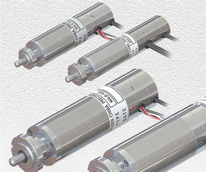
2 Ultra Miniaturized Linear Actuator Ultra Compact 1628 mm 630 mm Rated Thrust 1.56 kgf High Resolution m Unidirectional Repeatable Accuracy 320 m Bidirectional Repeatable Accuracy 525 m Bidirectional Positioning Accuracy 1050 m Special Features Ultra miniaturized AC servo linear actuators are the compact and light linear actuators, which enable precision positioning. The motor section adapts an AC servo motor of hollow structure and the encoder section adopts an optical rotary encoder with ultra miniaturization and high resolution. Together with these devices, the direct design without gearhead achieves the precision positioning of high resolution. MAB and MALB series utilizes ball screw to accomplish high speed and long life. MALS and MALB series are cost-effective models, which largely reduce the prices, but maintain the high precision positioning. The compact and light multifunctional driver was specially developed for this AC servo linier actuator. With the sinusoidal wave and gain low, this actuator has a smooth motion and positions itself without vibration, the most crucial for the linear actuator. The actuator is easily adaptable to be used in vacuum chambers or clean rooms, and can also be applied to a wide range of applications, such as production, inspection and experimental equipment in optical and semiconductor industries. Contents Reference to Model No.Drawing of Actuator FixingSystem ConfigurationP.2 Linear Actuator for General Environment MALS-D18 Series NEW Standard type (Cost-effective Model) P.3 MAS-D16 Series Standard Type P.4 MALS-D23 Series NEW Standard Type (Cost-effective Model) P.5 MAS-D23 Series Standard Type P.6 MALB-D28 Series NEW High Speed / Long Life Type(Cost-effective Model) P.7 MAB-D28 Series High Speed / Long Life Type P.8 Models for Special Environments MASC-D16 Series Linear Actuator for Clean Room P.9 MASC-D23 Series Linear Actuator for Clean Room P.10 MAVB-D28 Series High Vacuum P.11 MASG-D23 Series Chemical Cleanliness P.12 Cautions for Handling Products P.13 Control Driver LAD-01 Series NEW P.15 P.16 BSD-11, BSD-06 Series P.17 P.18 Cable P.19 P.20 Term Definition / Accuracy Measurement P.21 P.22 1
3 Model No. MAS - D23 H Type : : : : : : : S : Standard type LS : Standard type(cost-effective Model) B : Ball screw type LB : Ball screw type(cost-effective Model) SC : for clean room VB : for vacuum condition SG : for chemical cleanliness Outer diameter Tip shape 03: cable length is 200mm Standard cable length is 2m when no code is written at this position. H : Tip with flat point R : Tip with spherical point N : Tip with tapped hole (For MAB, MALB and MALS only) Drawing of Actuator Fixing Use an accompanying screw nut to fix the actuator to a locking plate. Accompanying screw nut for fixing the actuator Locking Plate Note 1) Use the accompanying screw nut to fix the actuator to your equipment. Desired accuracy may not be obtained when the actuator housing is clenched for fixing. Note 2) The malfunction of shaft slide is concerned when the hardness of locking plate is insufficient and the screw nut is tightened too strongly. System Configuration Positioning Controller Driver Cable AC AC Servo Linear Actuator DC24V DC24V Power = Products of our company 2
4 MALS-D18 Series NEW 6/ 10/ 20 mm 1.5 kgf Rated thrust 0.5 m Resolution Cost-Effective Model SF Tube Standard Type Nut Flat tip Original position with tapped hole type : 1.5 mm Add -03 at the last part of model number with order when 200 mm cable length is required. Specification Parameter Rated thrust Resolution Max speed Screw lead Unidirectional repeatable accuracy Bidirectional repeatable accuracy Bidirectional positioning accuracy Average reversal error Limit sensor Length Weight Diameter Model Flat tip : H type Spherical tip : R type Tapped hole : N type M2 with depth of 4 (Note 6) Note 1) Use the accompanying screw nut to fix the actuator to your equipment. Desired accuracy may not be obtained when the actuator housing is clenched for fixing. Note 2) The actuator shaft can receive a load in the both of forward and backward thrust directions. Use springs or something similar to apply pre-load to the shaft in either one direction at the operation. Backlash is concerned and desired accuracy may not be obtained when no pre-load is applied to the shaft. We perform the accuracy measurements by applying the pre-load of 800gf in the backward thrust direction at our shipping inspection. Please be careful not to place more than a rated trust in a forward thrust direction at a time of installation. Note 3) The actuator cable is not designed to withstand repeated bending stress. Please contact us if the cable receives repeated bending stress. Note 4) The encoders of these models have 2 channels only and have no Z phase. Note 5) As to the original position, refer to the page of term definition. Note 6) Torque loaded on a rod of actuator need to be less than 1 Nm when installing a screw to a hole in the tip of N type. Torque of over 1 Nm may cause a deterioration of actuator s precision. Safety Mechanism The damper system is set at the front end of stroke and limit sensor is installed at the rear end. Compatibility The mounting section of this linear actuator is compatible with manual micrometer. Special Driver Please use the driver LAD-01 series (Recommend), BSD-06 series which was specially developed for this actuator. Extension Cable The encoder is open collector type. The transmission distance may be extended by the use of LAD-01D-012 or BSD-06D-012 (good for line driver type) with an extension cable. 3
5 MAS-D16 Series 6/ 10/ 20 mm 2 kgf Rated thrust 0.25 m Resolution Spherical tip SF Tube Standard Type (Extra Fine) Nut Flat tip Original position Add -03 at the last part of model number with order when 200 mm cable length is required. Specification Parameter Model Rated thrust Resolution Max speed Screw lead Unidirectional repeatable accuracy Bidirectional repeatable accuracy Bidirectional positioning accuracy Average reversal error Limit sensor Length Weight Diameter Note 1) Use the accompanying screw nut to fix the actuator to your equipment. Desired accuracy may not be obtained when the actuator housing is clenched for fixing. Note 2) The actuator shaft can receive a load in the both of forward and backward thrust directions. Use springs or something similar to apply pre-load to the shaft in either one direction at the operation. Backlash is concerned and desired accuracy may not be obtained when no pre-load is applied to the shaft. We perform the accuracy measurements by applying the pre-load of 800gf in the backward thrust direction at our shipping inspection. Please be careful not to place more than a rated trust in a forward thrust direction at a time of installation. Note 3) The actuator cable is not designed to withstand repeated bending stress. Please contact us if the cable receives repeated bending stress. Safety Mechanism The damper system is set at the front end of stroke and limit sensor is installed at the rear end. Compatibility The mounting section of this linear actuator is compatible with manual micrometer. Special Driver Please use the driver LAD-01 series (Recommend), BSD-11 series which was specially developed for this actuator. Extension Cable The encoder is open collector type. The transmission distance may be extended by the use of LAD-01D-012 or BSD-11D-012 (good for line driver type) with an extension cable. 4
6 MALS-D23 Series NEW 10/ 15/ 25 mm 4 kgf Rated thrust 0.5 m Resolution Cost-Effective Model SF Tube Standard Type Specification Nut Flat tip Original position with tapped hole type : 1.5 mm Add -03 at the last part of model number with order when 200 mm cable length is required. Parameter Rated thrust Resolution Max speed Screw lead Unidirectional repeatable accuracy Bidirectional repeatable accuracy Bidirectional positioning accuracy Average reversal error Limit sensor Length Weight Diameter Model Flat tip : H type Spherical tip : R type Tapped hole : N type M3 with depth of 5 (Note 6) Note 1) Use the accompanying screw nut to fix the actuator to your equipment. Desired accuracy may not be obtained when the actuator housing is clenched for fixing. Note 2) The actuator shaft can receive a load in the both of forward and backward thrust directions. Use springs or something similar to apply pre-load to the shaft in either one direction at the operation. Backlash is concerned and desired accuracy may not be obtained when no pre-load is applied to the shaft. We perform the accuracy measurements by applying the pre-load of 800gf in the backward thrust direction at our shipping inspection. Note 3) The actuator cable is not designed to withstand repeated bending stress. Please contact us if the cable receives repeated bending stress. Note 4) The encoders of these models have 2 channels only and have no Z phase. Note 5) As to the original position, refer to the page of term definition. Note 6) Torque loaded on a rod of actuator need to be less than 1 Nm when installing a screw to a hole in the tip of N type. Torque of over 1 Nm may cause a deterioration of actuator s precision. Safety Mechanism The damper system is set at the front end of stroke and limit sensor is installed at the rear end. Compatibility The mounting section of this linear actuator is compatible with manual micrometer. Special Driver Please use the driver LAD-01 series (Recommend), BSD-06 series which was specially developed for this actuator. Extension Cable The encoder is open collector type. The transmission distance may be extended by the use of LAD-01D-012 or BSD-06D-012 (good for line driver type) with an extension cable. 5
7 MAS-D23 Series 10/ 15/ 25 mm 6 kgf Rated thrust 0.25 m Resolution Spherical tip Standard Type Nut Flat tip Original position Add -03 at the last part of model number with order when 200 mm cable length is required. Specification Parameter Model Rated thrust Resolution Max speed Screw lead Unidirectional repeatable accuracy Bidirectional repeatable accuracy Bidirectional positioning accuracy Average reversal error Limit sensor Length Weight Diameter Note 1) Use the accompanying screw nut to fix the actuator to your equipment. Desired accuracy may not be obtained when the actuator housing is clenched for fixing. Note 2) The actuator shaft can receive a load in the both of forward and backward thrust directions. Use springs or something similar to apply pre-load to the shaft in either one direction at the operation. Backlash is concerned and desired accuracy may not be obtained when no pre-load is applied to the shaft. We perform the accuracy measurements by applying the pre-load of 800gf in the backward thrust direction at our shipping inspection. Note 3) The actuator cable is not designed to withstand repeated bending stress. Please contact us if the cable receives repeated bending stress. Safety Mechanism The damper system is set at the front end of stroke and limit sensor is installed at the rear end. Compatibility The mounting section of this linear actuator is compatible with manual micrometer. Special Driver Please use the driver LAD-01 series (Recommend), BSD-11 series which was specially developed for this actuator. Extension Cable The encoder is open collector type. The transmission distance may be extended by the use of LAD-01D-012 or BSD-11D-012 (good for line driver type) with an extension cable. 6
8 MALB-D28 Series NEW 10/ 30 mm 5 kgf Rated thrust m Resolution with tapped hole M3 with depth of 5 Cost-Effective Model High Speed/ Long Life Type SF Tube Specification Parameter Nut Rated thrust Short time max thrust Resolution Max speed Screw lead Unidirectional repeatable accuracy Bidirectional repeatable accuracy Bidirectional positioning accuracy Average reversal error Limit sensor Length Weight Diameter 3-M3 with depth of 4 on24circumference Flat tip Original position with tapped hole type : 1.5 mm Model Add -03 at the last part of model number with order when 200 mm cable length is required. Flat tip : H type Spherical tip : R type M3 with depth of 5 Note 1) Use the accompanying screw nut to fix the actuator to your equipment. Desired accuracy may not be obtained when the actuator housing is clenched for fixing. Note 2) The actuator shaft can receive a load in the both of forward and backward thrust directions. Use springs or something similar to apply pre-load to the shaft in either one direction at the operation. Backlash is concerned and desired accuracy may not be obtained when no pre-load is applied to the shaft. We perform the accuracy measurements by applying the pre-load of 800gf in the backward thrust direction at our shipping inspection. Note 3) The actuator cable is not designed to withstand repeated bending stress. Please contact us if the cable receives repeated bending stress. Note 4) The relative position between the tapped hole for M3 set-screw and the cable is arbitrary. Note 5) The encoders of these models have 2 channels only and have no Z phase. Note 6) As to the original position, refer to the page of term definition. Tapped hole : N type 7 Safety Mechanism The damper systems are set at the both ends of stroke and limit sensor is installed at the rear end. The actuator shaft may move when a load is applied to it under the condition of no current since the actuator is unequipped with a built-in brake mechanism. Therefore, the customer may need safety measures to protect the equipment. High speed and long life High speed and long life operation is realized by the application of ball screw. Special Driver Please use the driver LAD-01 series (Recommend), BSD-06 series which was specially developed for this actuator. Extension Cable The encoder is open collector type. The transmission distance may be extended by the use of LAD-01D-012 or BSD-06D-012 (good for line driver type) with an extension cable.
9 MAB-D28 Series 10/ 30 mm 5 kgf Rated thrust 0.5 m Resolution High Speed / Long Life Type with tapped hole M3 with depth of 5 3-M3 with depth of 4 on24circumference Specification Parameter Nut Rated thrust Short time max thrust Resolution Max speed Screw lead Unidirectional repeatable accuracy Bidirectional repeatable accuracy Bidirectional positioning accuracy Average reversal error Limit sensor Length Weight Diameter Flat tip Original position with tapped hole type: 6mm Model Note 1) Use the accompanying screw nut to fix the actuator to your equipment. Desired accuracy may not be obtained when the actuator housing is clenched for fixing. Note 2) The actuator shaft can receive a load in the both of forward and backward thrust directions. Use springs or something similar to apply pre-load to the shaft in either one direction at the operation. Backlash is concerned and desired accuracy may not be obtained when no pre-load is applied to the shaft. We perform the accuracy measurements by applying the pre-load of 800gf in the backward thrust direction at our shipping inspection. Note 3) The actuator cable is not designed to withstand repeated bending stress. Please contact us if the cable receives repeated bending stress. Note 4) The relative position between the tapped hole for M3 set-screw and the cable is arbitrary. Add -03 at the last part of model number with order when 200 mm cable length is required. Flat tip : H type Spherical tip : R type Tapped hole : N type M3 with depth of 5 Safety Mechanism The damper systems are set at the both ends of stroke and limit sensor is installed at the rear end. The actuator shaft may move when a load is applied to it under the condition of no current since the actuator is unequipped with a built-in brake mechanism. Therefore, the customer may need safety measures to protect the equipment. High speed and long life High speed and long life operation is realized by the application of ball screw. Special Driver Please use the driver LAD-01 series (Recommend), BSD-11 series which was specially developed for this actuator. Extension Cable The encoder is open collector type. The transmission distance may be extended by the use of LAD-01D-012 or BSD-11D-012 (good for line driver type) with an extension cable. 8
10 Models for Special Environments MASC-D16 Series Linear Actuator for Clean Room Applicable to Clean Class 100 6/ 10/ 20 mm 1.5 kgf Rated thrust 0.25 m Resolution Spherical tip Clean SF Tube Specification Nut Flat tip Original position Add -03 at the last part of model number with order when 200 mm cable length is required. Parameter Model Rated thrust Resolution Max speed Screw lead Unidirectional repeatable accuracy Bidirectional repeatable accuracy Bidirectional positioning accuracy Average reversal error Limit sensor Length Weight Diameter Note 1) The shaft moves in the direction of the arrow when the motor rotates in CW direction. Note 2) Always use the limit switch. If not, the shaft may retrieve too deeply and never come out. Note 3) The Logic of the limit switch is normally " Close ". Please connect the limit switch to the higher rank controller and adjust the switch so as to stop the pulse output when the signal is ON. Note 4) The actuator shaft can receive a load in the both of forward and backward thrust directions. Use springs or something similar to apply pre-load to the shaft in either one direction at the operation. Backlash is concerned and desired accuracy may not be obtained when no pre-load is applied to the shaft. We perform the accuracy measurements by applying the pre-load of 800gf in the backward thrust direction at our shipping inspection. Please be careful not to place more than a rated trust in a forward thrust direction at a time of installation. Note 5) The actuator cable is not designed to withstand repeated bending stress. Please contact us if the cable receives repeated bending stress. Safety Mechanism The damper system is set at the front end of stroke and limit sensor is installed at the rear end. Compatibility The mounting section of this linear actuator is compatible with manual micrometer. Special Driver Please use the driver LAD-01 series (Recommend), BSD-11 series which was specially developed for this actuator. Extension Cable The encoder is open collector type. The transmission distance may be extended by the use of LAD-01D-012 or BSD-11D-012 (good for line driver type) with an extension cable. 9
11 Models for Special Environments MASC-D23 Series Linear Actuator for Clean Room Applicable to Clean Class / 15/ 25 mm 3 kgf Rated thrust 0.25 m Resolution Spherical tip Clean Specification Parameter Rated thrust Resolution Max speed Screw lead Unidirectional repeatable accuracy Bidirectional repeatable accuracy Bidirectional positioning accuracy Average reversal error Limit sensor Length Weight Diameter Nut Flat tip Original position Model Add -03 at the last part of model number with order when 200 mm cable length is required. Note 1) The shaft moves in the direction of the arrow when the motor rotates in CW direction. Note 2) Always use the limit switch. If not, the shaft may retrieve too deeply and never come out. Note 3) The Logic of the limit switch is normally " Close ". Please connect the limit switch to the higher rank controller and adjust the switch so as to stop the pulse output when the signal is ON. Note 4) The actuator shaft can receive a load in the both of forward and backward thrust directions. Use springs or something similar to apply pre-load to the shaft in either one direction at the operation. Backlash is concerned and desired accuracy may not be obtained when no pre-load is applied to the shaft. We perform the accuracy measurements by applying the pre-load of 800gf in the backward thrust direction at our shipping inspection. Note 5) The actuator cable is not designed to withstand repeated bending stress. Please contact us if the cable receives repeated bending stress. Safety Mechanism The damper system is set at the front end of stroke and limit sensor is installed at the rear end. Compatibility The mounting section of this linear actuator is compatible with manual micrometer. Special Driver Please use the driver LAD-01 series (Recommend), BSD-11 series which was specially developed for this actuator. Extension Cable The encoder is open collector type. The transmission distance may be extended by the use of LAD-01D-012 or BSD-11D-012 (good for line driver type) with an extension cable. 10

12 MAVB-D28 Series 10-6 Pa Specification 10/ 15/ 25 mm 2 kgf Rated thrust m Resolution Nut Flat Tip Note1 Models for Special Environments Linear Actuator for Vacuum High Vacuum Original Position Correspondence Pressure : 10-6 Pa Motor Cable Sensor Cable Positional relationship is arbitrary Limit Sensor Wire The cable ends are not fabricated. Parameter Model Rated thrust Resolution Max speed Screw lead Unidirectional repeatable accuracy Bidirectional repeatable accuracy Bidirectional positioning accuracy Average reversal error Limit sensor Sensor Allowable temperature limit Emitted Gas Speed (Note 5) Length Diameter Contact CS Touch Sensor (Normal Close) Resolver (Excitation to 1 phase Outputs from 2 phases) 1Pa Torr Wiring Color Motor Cable Note 1) The shaft moves in the direction of the arrow when the motor rotates in CW direction. Note 2) Always use the limit switch. If not, the shaft may retrieve too deeply and never come out. Note 3) The Logic of the limit switch is normally " Close ". Please connect the limit switch to the higher rank controller and adjust the switch so as to stop the pulse output when the signal is ON. Note 4) The actuator shaft can receive a load in the both of forward and backward thrust directions. Use springs or something similar to apply pre-load to the shaft in either one direction at the operation. Backlash is concerned and desired accuracy may not be obtained when no pre-load is applied to the shaft. We perform the accuracy measurements by applying the pre-load of 800gf in the backward thrust direction at our shipping inspection. Note 5) This is not guaranteed value but representative value. 1Pa Torr Resolver Cable U Phase Red V Phase Black W Phase White White Green Red Blue Black Driver Please contact us for the details about the driver. Yellow 11

13 MASG-D23 Series 10/ 15/ 25 mm 3 kgf Rated thrust 0.25 m Resolution Spherical tip Models for Special Environments Chemical Cleanliness Chemical Cleanliness Specification Nut Flat tip Original position Add -03 at the last part of model number with order when 200 mm cable length is required. Parameter Model Rated thrust Resolution Max speed Screw lead Unidirectional repeatable accuracy Bidirectional repeatable accuracy Bidirectional positioning accuracy Average reversal error Limit sensor Length Weight Diameter Note 1) The shaft moves in the direction of the arrow when the motor rotates in CW direction. Note 2) Always use the limit switch. If not, the shaft may retrieve too deeply and never come out. Note 3) The Logic of the limit switch is normally " Close ". Please connect the limit switch to the higher rank controller and adjust the switch so as to stop the pulse output when the signal is ON. Note 4) The actuator shaft can receive a load in the both of forward and backward thrust directions. Use springs or something similar to apply pre-load to the shaft in either one direction at the operation. Backlash is concerned and desired accuracy may not be obtained when no pre-load is applied to the shaft. We perform the accuracy measurements by applying the pre-load of 800gf in the backward thrust direction at our shipping inspection. Note 5) The actuator cable is not designed to withstand repeated bending stress. Please contact us if the cable receives repeated bending stress. 12
14 Cautions for Handling Products Products and other accompanying items are high precision products. All the cautions and warnings listed below should be properly understood and observed. Use the products after fully acquiring the product knowledge and confirming the safety handlings. Minimal cautions for safety use are followings. Caution at unpacking Perform visual inspection and confirm the model number when receiving the products. Cautions for handling Check the wire connection firstly. Faulty wiring shall cause malfunctions and defects. Do not pull the actuator cable and bend the root of cable. It may cause defects. Our actuator does not have ground terminals. Use the motor housing for the earth ground. Do not hit or add radial overload to the shaft. Do not add impermissible thrust overload to the shaft. It shall damage the products. Refer toactuator Fixingon P. 2 for the method. Use the screws, which are prescribed in the drawings, for driver and accompanying items. It shall damage the boards and cause malfunction, electric leakage and ignition, especially when excessively long screws are used for the driver. The life of actuator and accompanying items shall be affected by the load condition, operation mode and use environment. Fully perform the machine operation test. Do not use and store the products under the environment, which stores the materials of corrosive or poisonous gas. Avoid the intrusion of dust, droplet and oil into the products. Stop the operation and turn off the power when smoke, excess heat, abnormal smell, abnormal sound and abnormal vibration are perceived. Additional Caution Do not disassemble the products, but report it and return them when you find troubles. We perform the investigation and repair only when the products are returned properly. 13
15 Memo 14
 Special Features This motor driver is designed with a PWM control method to output 3 phase sine wave.")
16 LAD-01 Series Control Driver For Linear Actuator NEW LAD-01 Series LAD-01C-012 for Open Collector LAD-01D-012 for Line Driver Parameters and gains can be set by serial communication through USB cable. Outside Configuration, Install Dimension (Unit: mm) Special Features This motor driver is designed with a PWM control method to output 3 phase sine wave. This motor driver is designed for exclusive use of our ultra miniaturized linear actuators. Two types of preprogrammed gain setting can be switched by input signal. M3 Tap for a frame ground. Metal cover 4-4 hole Aluminum chassis to hold a circuit board Circuit Configuration DC/DC CONV. 24 V Power-supply to drive motor 0 V USB MINI-B USB MINI-B Connector Forward Backward USB USB Transceiver Pulse Counter I/O E2PROM Serial I/O Process to set up parameters Micro Controller /SVON /GLOW /RES /CLR /GAIN /TRQ /ORZ EMG /LSF /LSR /READY /ALM /INP IO IO Port Position command I/O Position controller Input/ output control ω cos sin i d =0 Speed controller i q cos i d i q sin Current controller v d v q Current controller d-q/ 3-phase a.c.ordinate converter 3 d-q d-q/ 3 3-phase a.c./d-q ordinate converter i v 12bit A/D i converter u v u v v v w PWM output 3 Circuit to detect current of motor Circuit to drive 3-phase motor Linear Actuator /ORGF /LSFM /LSRM EAM EBM EZM RS-422A Line Driver RS-422A Speed ω mechanical angle electric angle Speed / position signal processor Pulse Counter Encoder 15
17 Specification LAD-01 Model LAD-01 Series Input Power Supply DC 24V Continuous Rated Output Current 3 Arms Max Rated Output Current 10 A peak Control System Positioning Control Encoder Input A B Z (MALS / MALB series has no Z phase.) Hall sensor U V W (Hall IC) MAS-D16 16kHz MAB-D28 100kHz Input Max Frequency MASC-D16 MAS-D23 16kHz 20kHz MALS-D18 MALS-D23 8kHz 10kHz MASC-D23 20kHz MALB-D28 64kHz Positioning Accuracy 1 pulse of encoder resolution Multiplication function of encoder 4 multiplication function Control multiplication function 2 pulse systems: fixed 4 multiplications, others: 1 multiplication. Operating temperature 0 50 Operating humidity Below 85%RH without bedewing Storage temperature 20 to 85without bedewing Input Signals Pulse input system Selectable with parameter setting 1.2 pulse systemcw or CCW pulse system 2.1 pulse systempulse, Direction, Input 3.2-phase pulse system (Input is isolated by photo coupler) Reset input Alarm output reset, Residual pulse reset, Low active logic. Limit sensor input LSF (CW prohibition), LSR (CCW prohibition) (motor-free input) Not available G-Low input Low active is the logic of Gain Low (gain lowering due to the reduction of vibration at stoppage) Deviation clear Reset residual pulse, Low active Gain switching Switchable to 2 types of preprogrammed gain setting, Low active Start of retrieving original point Execute searching of an original point with a preprogrammed mode, Low active Output Signals INP Output In-position output can be set within a range from 0 to 15 pulse, Low active Alarm output It is output when encoder disconnection or full torque or full count or overheat occurs. (Encoder disconnection alarm is available only for a line driver type.) Cause of alarm is expressed by a number of times of flushing Encoder output A B Z Equivalent to RS-422 output Limit output Input from limit sensor is output by photo coupler Completion of searching an original point Ready Control Functions Power supply gain It is output when a search of original point is completed by a start signal to retrieve an original point. It is output when command pulse is ready to be input with the servo activated. Speed proportionate gain Speed integration gain Adjustable by parameter setting Positional gain Display Functions PWR Power ( 24V) SV Light up at the time of servo activation ALM Light up at the time of alarm occurrence. INP Residual deviation is within in-position setting point ORZ Light up when a search of original point is completed by a start signal to retrieve an original point. 16
 Special Features Driver by 3-phase sine wave PWM. Driver specially designed for our ultra compact actuator.")
18 BSD-11 BSD-06 Series Control Driver For Linear Actuator BSD-11 Series BSD-11C-012 for Open Collector BSD-11D-012 for Line Driver BSD-06 Series MALS / MALB for Cost-effective models, MALS/MALB Series BSD-06C-012 for Open Collector BSD-06D-012 for Line Driver Outside Configuration (Unit: mm) Special Features Driver by 3-phase sine wave PWM. Driver specially designed for our ultra compact actuator. Compact size attained by the full digital servo control where ASIC and CPU are incorporated. DC 24V single power supply. (built-in power control) Install Dimension(Unit: mm) 3-M3 Tap 2-M3 Tap Circuit Configuration Forward Backward STOP GLOW RESET ALARM INP Z A B Vref LSS LSF LSR 24V V Gate array Position command Position controller Gate array To 3-phase Transistor module Micro Controller cos sin i d =0 cos sin Speed controller i q Speed detector i d i q Current controller v d v q Current controller d-q/ 3-phase a.c.ordinate converter 3 d-q d-q3 3-phase a.c./d-q ordinate converter i v v u v v v w mechanical angle electric angle 8ch A/D 8ch i u A/D converter PWM output To 3-phase transistor module Gate array Speed / position signal processor Proportional gain(during PI control) Integration gain Positional gain Feed forward gain Proportional gain (during P control) Linear Actuator Encoder 17 MALS/MALB series has no Z phase and you do not connect the pin.
19 Specification BSD-11 BSD-06 Model BSD-11 Series BSD-06 Series Input Power Supply DC 24V Continuous Rated Output Current 1.2 Arms Changeable by adjustment of heat radiation Max Rated Output Current 2.1 Arms Control System Positioning Control Encoder Input A B Z (MALS / MALB series has no Z phase.) Hall sensor U V W (Hall IC) Input Max Frequency MAS-D16 MASC-D16 MAS-D23 MASC-D23 MAB-D28 16kHz 16kHz 20kHz 20kHz 100kHz MALS-D18 MALS-D23 MALB-D28 8kHz 10kHz 64kHz Positioning Accuracy 1 pulse of encoder resolution Multiplication function of encoder 1, 2, 4 multiplication function Control multiplication function 1, 2, 4 multiplication function ( 4 is applicable only by 2-phase input) Operating temperature 0 40 Operating humidity Below 85%RH without bedewing Storage temperature 20 to 85without bedewing Weight 250g Input Signals Pulse input system [ Chosen by jumper circuit ] 1.2 pulse systemcw or CCW pulse system 2.1 pulse systempulse, Direction, Input 3. 2-phase pulse system (Input is isolated by photocoupler) Reset input Alarm output reset, Residual pulse reset, Low active logic. Limit sensor input LSF (CW prohibition), LSR (CCW prohibition), LSS (motor free) (motor-free input) Input logic of LSF or LSR is changeable by jumper circuit G-Low input Low active is the logic of Gain Low(gain lowering due to the reduction of vibration at stoppage) Gain at gain low is re-settable by volume Output Signals INP Output In-position output, which can be set within a range from 0 to 15 pulse, Low active Alarm output Alarm for encoder disconnection or full torque or full count or fin overheat. Alarm display on LED. Logic of low active Encoder output A B Z Another 5V power to A and B is required. (MALS / MALB series has no Z phase.) Limit output Input from limit sensor is output by photocoupler Control Functions LOOP Loop Gain (adjustment for integral TC and proportional gain) P Adjustment for proportional gain POS Adjustment for position loop gain GAIN Adjustment for gain low Display Functions PWR Power ( 24V) EE Encoder disconnection: Either phase of IC Hall / Either A or B phase of Line Driver FT Full torque alarm: Max current runs longer than 1 second FC Full count alarm: Overflows of deviation counters ( counts) OH Overheat alarm: Over 75 ( 5) at heat radiate fin IP Residual deviation is within in-position setting point PL Z Deviation polarity (residual deviation : display, : no display) Z-phase 18
20 MA RoHS RoHS Directive Compliance Products Thermal contraction tube 50 Cable Actuator connection cable This cable is used for open collector type. To actuator To driver Connectors for cable are accompanied with actuator and driver so that you can make your own cable by yourself (The shapes of connectors are different from the drawing). MA-321-XXX Extension cable with line driver box Direct connection type to driver for line driver. 40 Thermal contraction tube L To driver MA L=3m 50mm MA L=5m 70mm MA L=10m 100mm MA-322-XXX Extension cable with line driver box When MA-322-XXX connector is fixed to your panel unit. This cannot be directly connected to the driver MRP-25F01 HONDA TSUSHIN KOGYO CO., LTD. 2. DF1B-24DS-2.5RC HIROSE ELECTRIC CO., LTD. 3. H4P-SHF-AA J.S.T. Mfg. Co., Ltd L Attached connector MA L=3m 50mm MA L=5m 70mm MA L=10m 100mm MA Robot cable This cable is connected directly to the open collector type driver. This cable can be used only when the actuator, whose cable length is 200mm, is selected. Thermal contraction tube To actuator Thermal contraction tube To driver 2.5mMA (03)200mm The prompt transmission of electric current and signals is guaranteed only when the total cable length is within 2.5m for Open Collector. Please add -03 (actuator cable length:200mm) at the last part of Open Collector model type with MA MA mm Robot cable This cable can be used only when the actuator, whose cable length is 200mm, is selected. Thermal contraction tube To actuator Thermal contraction tube 2.5mMA (03)200mm The prompt transmission of electric current and signals is guaranteed only when the total cable length is within 2.5m for Open Collector. Please add -03 (actuator cable length:200mm) at the last part of Open Collector model type with MA
21 Reference Drawing of Combination with Cables Open Collector Type Driver MAS / MALS MAB / MALB MASC / MASG Driver for Line Driver MA MA-321-XXX Wiring by yourself MA-322-XXX Wiring by yourself ) e.g. When Linear Actuator connector is fi xed to your panel unit. ) MA-322-XXX e.g. When MA-322-XXX connector is fi xed to your panel unit. LAD-01C-012 BSD-11C The last code of Linear Actuator LAD-01D-012 BSD-11D-012 BSD-06C-012 MA MA (Robot cable) MA (Robot cable) -03 (200mm) MA-321-XXX MA-322-XXX Wiring by yourself BSD-06D-012 Wiring by yourself MA (Robot cable) MA (Robot cable) MA-321-XXX ) e.g. When Linear Actuator connector is fi xed to your panel unit. MA (Robot cable) MA-322-XXX ) MA-322-XXX e.g. When MA-322-XXX connector is fi xed to your panel unit. Wiring by yourself MA : (03) MA : It can be used as an extension cable by connecting to -03 Actuator. 2.5m Total Cable Length: Shorter than 2.5m 12.5m Total Cable Length: Shorter than 12.5m 20
22 Term Definition L [m] 10-3 P m L [mm]p [Pulse]m Traveling range of linear actuator shaft at forward and backward movements Rated Thrust Max thrust power including pre-load amount at the max speed of linear actuator Resolution This is a minimum traveling distance per 1 pulse transmitted from the driver, which is logically attained for the position control. It is calculated by the pulse train number of encoder, multiplying rate of driver and lead length of screw. L Resolution [m] 10-3 P m L: Screw Lead (mm), P: Encoder pulse train (Pulse), m: Multiplication Pre-load Load toward the thrust (backward) direction to reduce the gaps in lead screw and ball screw of shaft. Original Position Our company defines two ways of original position settings as followings. Definition A Linear Actuator Limit Sensor ON Limit Sensor OFF Encoder Z phase Backward Forward Forward Original Position You move the shaft toward the backward direction and stop it when the alarm of limit sensor is activated. You move the shaft at 10% of max speed toward the forward direction to deactivate the alarm and stop it when the first Z phase is detected. The above point is regarded as an original position. Definition B Linear Actuator Limit Sensor ON Limit Sensor OFF Backward Forward You move the shaft toward the backward direction and stop it when the alarm of limit sensor is activated. You move the shaft at 10% of max speed toward the forward direction, and stop it when the alarm is deactivated. The above point is regarded as the original position. Original Position Definition A B Model MAS Series MAB SeriesMAR SeriesMASC SeriesMASG Series MALS SeriesMALB Series Positioning Accuracy This indicates an absolute error at the position where the shaft stops at the target position. It is synonymous with absolute accuracy including repeatable accuracy. Repeatable Accuracy This means repeatability when you perform the positioning repeatedly. Average Reversal Error This is an average difference of stop positions when you operate the positioning to the target position from the forward and backward directions. Accuracy Measurement In accordance with JIS B 6201 (Machine Tool - General Rule of Test Method), CITIZEN CHIBA PRECISION performs the accuracy measurement and defines the accuracy. Linear Actuator Number of Positioning 1 Forward Backward Original Position P0 P1 P2 P3 P4 P5 P6 P7 P8 P9 Moving Direction Accuracy Measurement As indicated in Drawing 1, we operate the positioning to the target positions from the forward and backward directions five times. By investigating the difference (deviation) of target and actual stop positions, we calculate Unidirectional Repeatable Accuracy, Bidirectional Repeatable Accuracy, Bidirectional Positioning Accuracy and Average Reversal Error. 1 The following formula calculates the distance of 1 step from P.0~8. stroke mm 2 [mm] 8 stroke mm Distance of 1 step [mm] 8 1 Step We truncate less than 100 pulses from the number of pulse trains, which is transmitted 5 5 from the amount of 1 step. The following is the amount between P8~P9; stroke (amount of 1 step 8) stroke Drawing 1 21
23 Table-1 Number Definition In accordance with the above formula in the Drawing 1 and the difference (deviation) of target and actual stop positions, we calculate Unidirectional Repeatable Accuracy, Birectional Repeatable Accuracy, Bidirectional Positioning Accuracy and Average Reversal Error. Code Positioning from Forward Direction Definitional Identity Positioning from Backward Direction 1 Number of Target Stop Position 2 j th target position Actual stop point to the target position j on i th positionings from forward or backward direction Deviation between actual and target stop positions at Pj point on i th positionings from forward or backward direction Average deviation of actual stop positions to Pj point on 5 positionings 6 Reversal error at Pj point axispositioning accuracy at Pj Positioning point accuracy of kinetic 7 8 Limit of unidirectional positioning accuracy Calculating Formula Upper Limit Lower Limit 12 Bidirectional Repeatable Accuracy (of Kinetic Axis) 13 Bidirectional Positioning Accuracy (of Kinetic Axis) Estimate of average deviation at Pj point on unidierctional positioning Calcuration from width 9 Bidirectional Positioning Accuracy 10 Bidirectional Repeatable Accuracy Average Reversal Error Maximum value ofor Unidirectional Repeatable Accuracy (of Kinetic Axis) The drawing -2 is the graph, which is calculated from /xj, Pju, Pjl, Rj of Table-1. Rj is a figure, which is calculated from 3sj+3sj+ l B l in the graph P1 4 P2 P3 P4 P5 P6 P7 P8 /xj Pju Pjl Rj 3 2 Rj max /xj Pju Pjl 1 [m] error 0 A -1 Drawing Rjmax Rjmax Accuracy Definition Unidirectional Repeatable Accuracy This indicates the repeatability, which is attained by positioning from the forward or backward direction. We define the maximum value of Rjor Rjin Table -2 as unidirectional repeatable accuracy. Bidirectional Repeatable Accuracy We define the maximum value of Rjand Rjor Rjmax in Table -2 as bidirectional repeatable accuracy Bidirectional Positioning Accuracy This is the maximum difference between the target and actual stop positions and it includes bidirectional repeatable accuracy We define A in Table-2 as bidirectional positioning accuracy. Average Reversal Error The average value of reversal error Bj Regarding the above definitions, we investigate all the products at the shipping inspection. 22


24 Semiconductor Equipment: Stepper aligner, spincoater, dicing saw, turbo molecular pump, cleaning equipment, die bonder, equipment for test, inspection and high accuracy motion control including use in vacuum condition. Optical and Magnetic Disk Storage Equipment: Optical disk initializer, optical disk testing system, optical disk storage media certifi ers. Digital Imaging Equipment: Laser scanner with mirror / polygons, high-end laser printer, image setter and other high performance spinning scanning products. Medical Equipment: High-speed dental micro grinder, ultrasonic diagnosis, artifi cial heart, X-ray instruments and centrifugal separater. Laser and Optical Equipment: Laser marker, laser scanner, optical measuring equipment, image processor, optical fi ber splicing machine, laser microscope, optical connector equipment and electron microscope. Machine Tools, FA and Inspection Equipment: Robots, actuator, cardreader, high speed drilling machine, grinding machine, mirror polishing equipment, welding machine, contact lens lathers, 3-D measuring equipment and high speed winding machine. Technical data and products are subject to change without notice. For further information, please contact us or our authorized agent at any time. info@ccj.citizen.co.jp / , Yoshihashi, Yachiyo, Chiba , Japan Telephone : / Facsimile : info@ccj.citizen.co.jp /
/ Motor Specifications Direct Motor Drive Ball Screws / Precision Ball Screw type MB / MB MB Precision Ball Screw type MB / MoBo C3 5 5 Features A 5-p
 / Motor Specifications MB Precision Ball Screw type MB / MoBo C3 5 5 Features A 5-pahse Stepping Motor is mounted directly onto the shaft end of a C3 grade precision Ball Screw, which is suitable for high
Direct Motor Drive Lead Screws / Resin Lead Screw type RM / RM RM Resin Lead Screw type RM / Resin MoBo 2 MRH 2 Features A 2-phase Stepping Motor is m
 RM Resin Lead Screw typerm / Resin MoBo MRH Features A -phase Stepping Motor is mounted directly onto the shaft end of a Resin Lead Screw, which is multi-use product. Lead Screw Shaft is ideally constructed
Specification for Manual Pulse Generator, GFK-2262
 Specification change in Manual Pulse Generator () A) Abstract This document explains about the specification change in Manual Pulse Generator (). The production of the former specifications written in
SCR8-17XX Technical Data Optical Magnetic Brushless Coreless Encoder Motor Unitmm 5 Number of commutator segments Brushes Precious Metal Bearings Slee
 CORELESS MOTOR SCR8-17 SCR10-17 SCR10-25 SCR12-13 SCR12-18 SCR12-26 SCR13-20 SCR13-28 NEW SCR16-25 SCR16-35 SCR17-25 SCR17-35 SCR18-37 SC21-37 SC24-32 Smaller and higher-performance motors realized by
080906_…o…−…^…b…vVSCW
 Thyristor Type Single-Phase Power Regulator 2030 A 6A 150200A TOKYO RIKOSHA CO., LTD Latest VARITAP VSCW Series Achieved 1/2 the width (our company comparison). Free Power source of 100 to 240V specification.cover-type
alternating current component and two transient components. Both transient components are direct currents at starting of the motor and are sinusoidal
 Inrush Current of Induction Motor on Applying Electric Power by Takao Itoi Abstract The transient currents flow into the windings of the induction motors when electric sources are suddenly applied to the
FLA Brochure.indd
 Ultra-Flat Brushless DC Actuators FLA Series Ultra-Flat Actuators Integrate a High-Performance Speed Reducer and a Brushless DC Motor The new ultra-flat, ultra-light brushless actuators combine our high-precision/high-performance
WARNING To reduce the risk of fire or electric shock,do not expose this apparatus to rain or moisture. To avoid electrical shock, do not open the cabi
 ES-600P Operating Instructions WARNING To reduce the risk of fire or electric shock,do not expose this apparatus to rain or moisture. To avoid electrical shock, do not open the cabinet. Refer servicing
I N S T R U M E N T A T I O N & E L E C T R I C A L E Q U I P M E N T Pressure-resistant gasket type retreat method effective bulk compressibility Fro
 Cable Gland This is the s to use for Cable Wiring in the hazardous location. It is much easier to install and maintenance and modification compared with Conduit Wiring with Sealing Fitting. The Standard
0810_UIT250_soto
 UIT UNIMETER SERIES 250 201 Accumulated UV Meter Digital UV Intensity Meter Research & Development CD Medical Biotech Sterilization Exposure Bonding Manufacturing Curing Production Electronic Components
2
 8 23 26A800032A8000 31 37 42 51 2 3 23 37 10 11 51 4 26 7 28 7 8 7 9 8 5 6 7 9 8 17 7 7 7 37 10 13 12 23 21 21 8 53 8 8 8 8 1 2 3 17 11 51 51 18 23 29 69 30 39 22 22 22 22 21 56 8 9 12 53 12 56 43 35 27
2
 8 22 19A800022A8000 30 37 42 49 2 3 22 37 10 11 49 4 24 27 7 49 7 8 7 9 8 5 6 7 9 8 16 7 7 7 37 10 11 20 22 20 20 8 51 8 8 9 17 1 2 3 16 11 49 49 17 22 28 48 29 33 21 21 21 21 20 8 10 9 28 9 53 37 36 25
AC AC Servomotors Ultra Compact Hih Resolution Hih Power Special Feature Hih response and hih power are attained by adaptin NdFeB manet. Mechanical vi
 AC AC Servomotors Ultra Compact Hih Resolution Hih Power Special Feature Hih response and hih power are attained by adaptin NdFeB manet. Mechanical vibration is reduced by balancin the rotor. The slotless
LC304_manual.ai
 Stick Type Electronic Calculator English INDEX Stick Type Electronic Calculator Instruction manual INDEX Disposal of Old Electrical & Electronic Equipment (Applicable in the European Union
1 2 3
 INFORMATION FOR THE USER DRILL SELECTION CHART CARBIDE DRILLS NEXUS DRILLS DIAMOND DRILLS VP-GOLD DRILLS TDXL DRILLS EX-GOLD DRILLS V-GOLD DRILLS STEEL FRAME DRILLS HARD DRILLS V-SELECT DRILLS SPECIAL
cms.pdf
 RoHS compliant INTERNAL STRUTURE FEATURES Part name over Slider Housing Slider contact Fixed contact Terminal pin lick spring Ground terminal Material Steel (SP), Tin-plated Polyamide opper alloy, Gold-plated
The hand operated type HB unit is a worm gear drive which may be used for any valve or device requiring a 90 movement. The HB worm gear actuator is es
 The hand operated type HB unit is a worm gear drive which may be used for any valve or device requiring a 90 movement. The HB worm gear actuator is especially designed for operation of butterfly, plug
LM35 高精度・摂氏直読温度センサIC
 Precision Centigrade Temperature Sensors Literature Number: JAJSB56 IC A IC D IC IC ( ) IC ( K) 1/4 55 150 3/4 60 A 0.1 55 150 C 40 110 ( 10 ) TO-46 C CA D TO-92 C IC CA IC 19831026 24120 11800 ds005516
2
 8 24 32C800037C800042C8000 32 40 45 54 2 3 24 40 10 11 54 4 7 54 30 26 7 9 8 5 6 7 9 8 18 7 7 7 40 10 13 12 24 22 22 8 55 8 8 8 8 1 2 3 18 11 54 54 19 24 30 69 31 40 57 23 23 22 23 22 57 8 9 30 12 12 56
 6 4 4 9RERE6RE 5 5 6 7 8 9 4 5 6 4 4 5 6 8 4 46 5 7 54 58 60 6 69 7 8 0 9 9 79 0 4 0 0 4 4 60 6 9 4 6 46 5 4 4 5 4 4 7 44 44 6 44 8 44 46 44 44 4 44 0 4 4 5 4 8 6 0 4 0 4 4 5 45 4 5 50 4 58 60 57 54
2
 8 23 32A950S 30 38 43 52 2 3 23 40 10 33 33 11 52 4 52 7 28 26 7 8 8 18 5 6 7 9 8 17 7 7 7 38 10 12 9 23 22 22 8 53 8 8 8 8 1 2 3 17 11 52 52 19 23 29 71 29 41 55 22 22 22 22 22 55 8 18 31 9 9 54 71 44
K02LE indd
 I Linear Stage Table of Contents 1. Features... 1 2. Description of part Number... 1 3. Maximum Speed Limit... 2 4. Specifications... 3 5. Accuracy Grade... 4 6. Motor and Motor Adaptor Flange... 4 6-1
BS・110度CSデジタルハイビジョンチューナー P-TU1000JS取扱説明書
 C S0 CS Digital Hi-Vision Tuner C C C C S0-0A TQZW99 0 C C C C 4 5 6 7 8 9 C C C C C C C C C C C C C C C C C C C C C C C 0 FGIH C 0 FGIH C C C FGIH FG IH FGIH I H FGIH FGIH 0 C C # $ IH F G 0 # $ # $
19_22_26R9000操作編ブック.indb
 8 19R900022R900026R9000 25 34 44 57 67 2 3 4 10 37 45 45 18 11 67 25 34 39 26 32 43 7 67 7 8 7 9 8 5 7 9 21 18 19 8 8 70 8 19 7 7 7 45 10 47 47 12 47 11 47 36 47 47 36 47 47 24 35 8 8 23 12 25 23 OPEN
 6 4 45 7ZS 5 59 7 8 94 05 4 5 6 4 5 5 6 8 8 40 45 48 56 60 64 66 66 68 7 78 80 8 7 8 0 0 0 90 0 57 64 69 66 66 69 0 4 4 4 4 4 0 7 48 5 4 4 5 4 4 4 7 46 46 6 46 8 46 48 46 46 4 46 46 4 4 5 4 6 4 9 9 0
I N S T R U M E N T A T I O N & E L E C T R I C A L E Q U I P M E N T STW Symbol Symbol otary switch) 05 otary switch Symbol angle of notch 181
 05 otary switch Symbol angle of notch 181") These items are using an aluminum alloy cast, so the weight is corrosion-resistant and excel halo tolerance and is light-weight and it's about 1/3 compared with conventional cast iron and made of steel
These items are using an aluminum alloy cast, so the weight is corrosion-resistant and excel halo tolerance and is light-weight and it's about 1/3 compared with conventional cast iron and made of steel
 6 50G5S 3 34 47 56 63 http://toshibadirect.jp/room048/ 74 8 9 3 4 5 6 3446 4755 566 76373 7 37 3 8 8 3 3 74 74 79 8 30 75 0 0 4 4 0 7 63 50 50 3 3 6 3 5 4 4 47 7 48 48 48 48 7 36 48 48 3 36 37 6 3 3 37
 6 3 34 50G5 47 56 63 74 8 9 3 4 5 6 3446 4755 566 76373 7 37 3 8 8 3 3 74 74 79 8 30 75 0 0 4 4 0 7 63 50 50 3 3 6 3 5 4 4 47 7 48 48 48 48 7 36 48 48 3 36 37 6 3 3 37 9 00 5 45 3 4 5 5 80 8 8 74 60 39
fx-9860G Manager PLUS_J
 fx-9860g J fx-9860g Manager PLUS http://edu.casio.jp k 1 k III 2 3 1. 2. 4 3. 4. 5 1. 2. 3. 4. 5. 1. 6 7 k 8 k 9 k 10 k 11 k k k 12 k k k 1 2 3 4 5 6 1 2 3 4 5 6 13 k 1 2 3 1 2 3 1 2 3 1 2 3 14 k a j.+-(),m1
 6 4 45 ZS7ZS4ZS 5 59 7 8 94 05 4 5 6 4 5 5 6 8 8 40 45 48 56 60 64 66 66 68 7 78 80 8 7 8 0 0 0 90 0 0 4 4 4 4 6 57 64 69 66 66 66 69 4 0 7 48 5 4 4 5 4 4 4 7 46 46 6 46 8 46 48 46 46 4 46 46 4 4 5 4
untitled
 1.0 1. Display Format 8*2 Character 2. Power Supply 3.3V 3. Overall Module Size 30.0mm(W) x 19.5mm(H) x max 5.5mm(D) 4. Viewing Aera(W*H) 27.0mm(W) x 10.5mm(H) 5. Dot Size (W*H) 0.45mm(W) x 0.50mm(H) 6.
 5 30 B36B3 4 5 56 6 7 3 4 39 4 69 5 56 56 60 5 8 3 33 38 45 45 7 8 4 33 5 6 8 8 8 57 60 8 3 3 45 45 8 9 4 4 43 43 43 43 4 3 43 8 3 3 7 6 8 33 43 7 8 43 40 3 4 5 9 6 4 5 56 34 6 6 6 6 7 3 3 3 55 40 55
 5 7 3AS40AS 33 38 45 54 3 4 5 4 9 9 34 5 5 38 6 8 5 8 39 8 78 0 9 0 4 3 6 4 8 3 4 5 9 5 6 44 5 38 55 4 4 4 4 5 33 3 3 43 6 6 5 6 7 3 6 0 8 3 34 37 /78903 4 0 0 4 04 6 06 8 08 /7 AM 9:3 5 05 7 07 AM 9
 5 11 3 1....1 2. 5...4 (1)...5...6...7...17...22 (2)...70...71...72...77...82 (3)...85...86...87...92...97 (4)...101...102...103...112...117 (5)...121...122...123...125...128 1. 10 Web Web WG 5 4 5 ²
2 3
 * This device can only be used inside Japan in areas that are covered by subscription cable TV services. Because of differences in broadcast formats and power supply voltages, it cannot be used in overseas
 L C -6D Z3 L C -0D Z3 3 4 5 6 7 8 9 10 11 1 13 14 15 16 17 OIL CLINIC BAR 18 19 POWER TIMER SENSOR 0 3 1 3 1 POWER TIMER SENSOR 3 4 1 POWER TIMER SENSOR 5 11 00 6 7 1 3 4 5 8 9 30 1 3 31 1 3 1 011 1
H8000操作編
 8 26 35 32H800037H800042H8000 49 55 60 72 2 3 4 48 7 72 32 28 7 8 9 5 7 9 22 43 20 8 8 8 8 73 8 13 7 7 7 55 10 49 49 13 37 49 49 49 49 49 49 12 50 11 76 8 24 26 24 24 6 1 2 3 18 42 72 72 20 26 32 80 34
Galvanometer Optical Scanner & Driver Special Features Low inertia and high torque Exact linearity and precise position control Superior temperature c
 Galvanometer Optical Scanner GVM-9 S GVM-9 L GVM-445 S GVM-445 L GVM-226 GVM-22 GVM-25 Built-in Optical Sensor Galvanometer Optical Coreless Scanner DC Motors http://ccj.citizen.co.jp/ RoHS RoHS Directive
MINAS取説アブソ警告クリア方法記載ミス_モータニュース…
 194 201 228 235 268 275 Absolute System Battery installation Initial installation Connect the lead wire from the battery unit top to its own connector. Wait for 5 minutes and then install the battery to
MIDI_IO.book
 MIDI I/O t Copyright This guide is copyrighted 2002 by Digidesign, a division of Avid Technology, Inc. (hereafter Digidesign ), with all rights reserved. Under copyright laws, this guide may not be duplicated
2 3 12 13 6 7
 2 8 17 42ZH700046ZH700052ZH7000 28 43 54 63 74 89 2 3 12 13 6 7 3 4 11 21 34 63 65 8 17 4 11 4 55 12 12 10 77 56 12 43 43 13 30 43 43 43 43 10 45 14 25 9 23 74 23 19 24 43 8 26 8 9 9 4 8 30 42 82 18 43
03-01 Senyouki.pdf
 Special Surface Treatment Rust-free under normal use conditions. No loss of precision due to rust. Minimum maintenance required. Stub Holder KH-E KH-EC1 Stub Holder KH-A 406 KH-E Quick Change Stub Holder
How to read the marks and remarks used in this parts book. Section 1 : Explanation of Code Use In MRK Column OO : Interchangeable between the new part
 Reservdelskatalog MIKASA MVB-85 rullvibrator EPOX Maskin AB Postadress Besöksadress Telefon Fax e-post Hemsida Version Box 6060 Landsvägen 1 08-754 71 60 08-754 81 00 info@epox.se www.epox.se 1,0 192 06
OPERATING INSTRUCTION RNTD Model NTD Model To the use r In order to use the torque driver properly and safely,please read the instructions before oper
 OPERATING INSTRUCTION RNTD Model NTD Model To the use r In order to use the torque driver properly and safely,please read the instructions before operation.if there are any questions,please contact a Tohnichi
How to read the marks and remarks used in this parts book. Section 1 : Explanation of Code Use In MRK Column OO : Interchangeable between the new part
 Reservdelskatalog MIKASA MT65H vibratorstamp EPOX Maskin AB Postadress Besöksadress Telefon Fax e-post Hemsida Version Box 6060 Landsvägen 1 08-754 71 60 08-754 81 00 info@epox.se www.epox.se 1,0 192 06
Z7000操作編_本文.indb
 2 8 17 37Z700042Z7000 46Z7000 28 42 52 61 72 87 2 3 12 13 6 7 3 4 11 21 34 61 8 17 4 11 4 53 12 12 10 75 18 12 42 42 13 30 42 42 42 42 10 62 66 44 55 14 25 9 62 65 23 72 23 19 24 42 8 26 8 9 9 4 11 18
0 C C C C C C C
 C * This device can only be used inside Japan in areas that are covered by subscription cable TV services. ecause of differences in broadcast formats and power supply voltages, it cannot be used in overseas
How to read the marks and remarks used in this parts book. Section 1 : Explanation of Code Use In MRK Column OO : Interchangeable between the new part
 Reservdelskatalog MIKASA MVC-50 vibratorplatta EPOX Maskin AB Postadress Besöksadress Telefon Fax e-post Hemsida Version Box 6060 Landsvägen 1 08-754 71 60 08-754 81 00 info@epox.se www.epox.se 1,0 192
I N S T R U M E N T A T I O N & E L E C T R I C A L E Q U I P M E N T box number basic type Standard Specification Material of Enclosure Material of F
 01 Flameproof Junction Box Junction Box Series Our junction boxes are designed and manufactured based on the Recommended Practices for Explosion-Protected Electrical Installations in General Industries
VE-GD21DL_DW_ZB
 V E-G D21D L V E-G D21D W 1 2 3 4 1 2 1 2 1 2 2 1 2 3 1 2 3 1 2 3 1 4 4 2 3 5 5 1 2 3 4 1 2 3 1 2 3 4 1 2 3 2006 Copyrights VisionInc. @. _ & $ % + = ^ 2011
内蔵ハードディスクユニット-20GB (PG-HD2E4H) 内蔵ハードディスクユニット-40GB (PG-HD4E4H)取扱説明書 HARD DISK DRIVE 20GB(PG-HD2E4H) HARD DISK DRIVE 40GB(PG-HD4E4H) USER'S GUIDE
 内蔵ハードディスクユニット-40GB (PG-HD4E4H)取扱説明書 HARD DISK DRIVE 20GB(PG-HD2E4H) HARD DISK DRIVE 40GB(PG-HD4E4H) USER'S GUIDE") B7FY-0351-02 J E J 1 J 1 2 3 2 4 J 3 4 Preface Thank you very much for purchasing the hard disk drive. This hard disk drive provides a IDE interface and can be installed in the 3.5-inch storage bay of
B7FY-0351-02 J E J 1 J 1 2 3 2 4 J 3 4 Preface Thank you very much for purchasing the hard disk drive. This hard disk drive provides a IDE interface and can be installed in the 3.5-inch storage bay of
How to read the marks and remarks used in this parts book. Section 1 : Explanation of Code Use In MRK Column OO : Interchangeable between the new part
 Reservdelskatalog MIKASA MCD-L14 asfalt- och betongsåg EPOX Maskin AB Postadress Besöksadress Telefon Fax e-post Hemsida Version Box 6060 Landsvägen 1 08-754 71 60 08-754 81 00 info@epox.se www.epox.se
VE-GP32DL_DW_ZA
 VE-GP32DL VE-GP32DW 1 2 3 4 5 6 1 2 3 4 1 1 2 3 2 3 1 1 2 2 2006 Copyrights VisionInc. @. _ & $ % + = ^ @. _ & $ % + = ^ D11 D12 D21
TH-42PAS10 TH-37PAS10 TQBA0286
 TH-42PAS10 TH-37PAS10 TQBA0286 2 4 8 10 11 17 18 20 21 22 23 24 25 26 27 28 29 30 31 32 33 38 42 44 46 50 51 52 53 54 3 4 5 6 7 8 3 4 1 2 9 5 6 1 4 2 3 5 6 10 11 1 2 3 4 12 13 14 TH-42PAS10 TH-42PAS10
LMC6022 Low Power CMOS Dual Operational Amplifier (jp)
") Low Power CMOS Dual Operational Amplifier Literature Number: JAJS754 CMOS CMOS (100k 5k ) 0.5mW CMOS CMOS LMC6024 100k 5k 120dB 2.5 V/ 40fA Low Power CMOS Dual Operational Amplifier 19910530 33020 23900
Low Power CMOS Dual Operational Amplifier Literature Number: JAJS754 CMOS CMOS (100k 5k ) 0.5mW CMOS CMOS LMC6024 100k 5k 120dB 2.5 V/ 40fA Low Power CMOS Dual Operational Amplifier 19910530 33020 23900
音響部品アクセサリ本文(AC06)PDF (Page 16)
PDF (Page 16)") Guide for Electret Condenser Microphones A microphone as an audio-electric converting device, whose audio pickup section has a structure of a condenser consisting of a diaphragm and a back plate opposite
Guide for Electret Condenser Microphones A microphone as an audio-electric converting device, whose audio pickup section has a structure of a condenser consisting of a diaphragm and a back plate opposite
GP05取説.indb
 E -G V P 05D L V E -G P 05D W Ni-MH + + + + + + + + + + + + + + + + + + + + + + + + + + + + + + + + + + 1 + 2 + 3 + 4 + 5 + 6 1 2 3 4 5 6 + + + 1 + + + + + + + + + + + + + + + + + + 1 A B C + D + E
取説_VE-PV11L(応用編)
") * 0 # VE-PV11L VE-PVC11L VE-PS109N 1 2 3 4 5 6 7 8 9 C H H H C H H H C C CAUTION:These telephones are for use in Japan only. They cannot be used in other countries because of differences in voltages, telephone
* 0 # VE-PV11L VE-PVC11L VE-PS109N 1 2 3 4 5 6 7 8 9 C H H H C H H H C C CAUTION:These telephones are for use in Japan only. They cannot be used in other countries because of differences in voltages, telephone
*Ł\”ƒ‚ä(DCH800)
") B B B B B B B B B C * This device can only be used inside Japan in areas that are covered by subscription cable TV services. Because of differences in broadcast formats and power supply voltages, it cannot
B B B B B B B B B C * This device can only be used inside Japan in areas that are covered by subscription cable TV services. Because of differences in broadcast formats and power supply voltages, it cannot
#表紙ドキュメントPDF書き出し用.indd
 MAGNETIC ENCODER MH-10 MR-13 MR-16 磁気式エンコダ モタと一体化設計とすること で 超小型ながら3 高分解能 ラインドライバ出力を 実現した磁気式エンコダです MR-13,MR-16 As designed in one unit with a motor, these magnetic encoders are very small, but are equipped
Standard products AR Series AR Anti-rotating device built-in type Standard products AR Series AR Anti-rotating device built-in type DDAAR-G Leadmm Tra
 Miniature Electric cylinder AR / CL シリーズ AR / CL Series / Internal Structure AR シリンダ / AR Cylinder 実 用 新 案 取 得 / Utility model resisterd 2 Compact Cylinder with 2-phase Hollow Stepping Motor integrated
Technische Beschreibung P82R SMD
 P26 halstrup-walcher GmbH http://www.krone.co.jp/ Stegener Straße 10 D-79199 Kirchzarten, Germany 124-0023 2-22-1 TEL:03-3695-5431 FAX:03-3695-5698 E-MAIL:sales-tokyo@krone.co.jp 530-0054 2-2-9F TEL:06-6361-4831
32720_MR-03_JSCC_CUP
 Before beginning assembly, please read these instructions thoroughly. THE FINEST RADIO CONTROL MODELS R MINI-Z Racer MR-03 Chassis Set ASF.4GHz JSCC CUP Edition Thank you for purchasing the Chassis Set
WE WESB WENB WESNB 428
 KH-A-NL Quick Change Stub Tapper Designed for use on KH-A spindle. Spindle Feed: All kinds of feed styles.for spindle feed other than pitch feed, use KH-A-NL in a condition where the tension feature always
DIN Connector_p2-25.qxd
 INDEX 1 DIN Connectors Varieties of DIN Connectors, Kinked Contact and One Touch Lock Metal Tab Kinked Contacts One Touch Lock Metal Tabs 2 Spec Sheet Soldering/Wire wrapping type Pitch Rated current 3A
PFQX2227_ZA
 V E -G P 05D B Ni-MH 1 2 3 4 5 6 1 2 3 4 5 6 A B C D E F 1 2 A B C 1 2 3 2 0 7 9 4 6 6 4 7 9 1 2 3 # 6 6 2 D11 D12 D21 D22 19 # # # # Ni-MH Ω Ω
xEffect_SG_MV_Part2_E_xEffect_SG_MV_E
 Miniature Circuit Breakers FAZ-NA, FAZ-RT, FAZ-DU SG56912 FAZ-NA/-RT/-DU According to UL 489, CSA C22.2 No. 5 and also IEC 60947-2 standard For Applications, wich are permitted for UL 1077 or CSA C22.2
Options Unit : mm Finger guards Color Model Surface treatment Nickel-chrome plating silver DC Fan 4mm Air Flo
 DC Fan 4mm sq. San Ace 4 1mm thick, 15mm thick (GA type), 15mm thick, 2mm thick (GA type), 2mm thick 28mm thick (GA type), 28mm thick (GE type) 28mm thick (GV type), 28mm thick General Specifications Material
FreeSpace.book
 IZA 190-HZ IZA 250-LZ ZA 190-HZ ZA 250-LZ FreeSpace Integrated Zone Amplifier/Zone Amplifier * 1. 2. 3. 4. 5. 6. 7. 8. 9. 2 2 10. 11. 12. 13. 14. 15. 16. 17. 40 C This product conforms to all EU Directive
1) 1) Props of preparation. Wire Scale Spike Cutter Hammer Tape Marker (, ) Rope(For Sezing) 2) 2) Marking A 22 A point Position of twenty-two times t
 1) Props of preparation. Wire Scale Spike Cutter Hammer Tape Marker (, ) Rope(For Sezing) 2) 2) Marking A 22 A point Position of twenty-two times t") 1) 1) Props of preparation. Wire Scale Spike Cutter Hammer Tape Marker (, ) Rope(For Sezing) 2) 2) Marking A 22 A point Position of twenty-two times the Dia, from the end of the rope. B A B point Position
1) 1) Props of preparation. Wire Scale Spike Cutter Hammer Tape Marker (, ) Rope(For Sezing) 2) 2) Marking A 22 A point Position of twenty-two times the Dia, from the end of the rope. B A B point Position
C H H H C H H H C C CUTION:These telephones are for use in Japan only. They cannot be used in other countries because of differences in voltages, tele
 VE-PV01LVE-PVW01LVE-PVC01L 1 4 7 2 3 5 6 8 9 * 0 # C H H H C H H H C C CUTION:These telephones are for use in Japan only. They cannot be used in other countries because of differences in voltages, telephone
- 1 -
 - 1 - - 2 - - 3 - - 4 - - 5 - - 6 - - 7 - - 8 - - 9 - - 10 - - 11 - - 12 - - 13 - - 14 - - 15 - 1 2 1-16 - 2 3 4 5 6 7-17 - 1 2 1 2 3 4-18 - 1 2 3 4 1 2-19 - 1 2 3 1 2-20 - 3 4 5 6 7 1-21 - 1 2 3 4-22
Microsoft Word - PCM TL-Ed.4.4(特定電気用品適合性検査申込のご案内)
") (2017.04 29 36 234 9 1 1. (1) 3 (2) 9 1 2 2. (1) 9 1 1 2 1 2 (2) 1 2 ( PSE-RE-101/205/306/405 2 PSE-RE-201 PSE-RE-301 PSE-RE-401 PSE-RE-302 PSE-RE-202 PSE-RE-303 PSE-RE-402 PSE-RE-203 PSE-RE-304 PSE-RE-403
(2017.04 29 36 234 9 1 1. (1) 3 (2) 9 1 2 2. (1) 9 1 1 2 1 2 (2) 1 2 ( PSE-RE-101/205/306/405 2 PSE-RE-201 PSE-RE-301 PSE-RE-401 PSE-RE-302 PSE-RE-202 PSE-RE-303 PSE-RE-402 PSE-RE-203 PSE-RE-304 PSE-RE-403
How to read the marks and remarks used in this parts book. Section 1 : Explanation of Code Use In MRK Column OO : Interchangeable between the new part
 Reservdelskatalog MIKASA MVC-88 vibratorplatta EPOX Maskin AB Postadress Besöksadress Telefon Fax e-post Hemsida Version Box 6060 Landsvägen 1 08-754 71 60 08-754 81 00 info@epox.se www.epox.se 1,0 192
0 C C C C C C
 C TU-HD50 TUNER TU - HD50 0 TU-HD50 C C C C S00-06C D D D 0 C C C C 4 5 6 7 8 9 C C C C C C C C C C C C C C C C C C C C C C TUNER TU - HD50 FGIH 0 C C C 0 FGIH C C C C C C FGIH FG IH FGIH I H FGIH FGIH
MOTIF XF 取扱説明書
 MUSIC PRODUCTION SYNTHESIZER JA 2 (7)-1 1/3 3 (7)-1 2/3 4 (7)-1 3/3 5 http://www.adobe.com/jp/products/reader/ 6 NOTE http://japan.steinberg.net/ http://japan.steinberg.net/ 7 8 9 A-1 B-1 C0 D0 E0 F0 G0
Description
 Metal Hybrid Inductor Description Metal Hybrid Inductor Magnetically shielded Suitable for Large Current Size: 4.3 x 4.3 x H2.1 mm Max. Product weight:.18g (Ref.) Halogen Free available Operating temperature
Options(Unit : mm) Finger guards Model :19-139E :19-139H 53 Surface treatment :Nickel-chrome plating (silver) :Cation electropainting (black) Inlet si
 Finger guards Model :19-139E :19-139H 53 Surface treatment :Nickel-chrome plating (silver) :Cation electropainting (black) Inlet si") AC Fan 6mm sq. San Ace 6 28mm thick, 38mm thick General Specifications Material Frame: Aluminum, Impeller:Plastics (Flammability: UL94V-1) Life Expectancy Varies for each model (L1: Survival rate: 9% at
AC Fan 6mm sq. San Ace 6 28mm thick, 38mm thick General Specifications Material Frame: Aluminum, Impeller:Plastics (Flammability: UL94V-1) Life Expectancy Varies for each model (L1: Survival rate: 9% at
00_1512_SLIMLINE_BOOK.indb
 PIECE type SLIM type Imbalance value Less interference type, ideal for deep machining Ideal for drilling 2 PIECE REGULAR type Rigidity value Nozzle type When compared to the slim type, it has more rigidity
Development of Induction and Exhaust Systems for Third-Era Honda Formula One Engines Induction and exhaust systems determine the amount of air intake
 Development of Induction and Exhaust Systems for Third-Era Honda Formula One Engines Induction and exhaust systems determine the amount of air intake supplied to the engine, and as such are critical elements
2
 L C -24K 9 L C -22K 9 2 3 4 5 6 7 8 9 10 11 12 11 03 AM 04 05 0 PM 1 06 1 PM 07 00 00 08 2 PM 00 4 PM 011 011 021 041 061 081 051 071 1 2 4 6 8 5 7 00 00 00 00 00 00 00 00 30 00 09 00 15 10 3 PM 45 00
Tab 5, 11 Tab 4, 10, Tab 3, 9, 15Tab 2, 8, 14 Tab 1, 7, 13 2
 COMPANION 20 MULTIMEDIA SPEAKER SYSTEM Owner s Guide Tab 5, 11 Tab 4, 10, Tab 3, 9, 15Tab 2, 8, 14 Tab 1, 7, 13 2 Tab1, 7, 13 Tab 2, 8, 14 Tab 3, 9, 15 Tab 4, 10, Tab 5, 11 This product conforms to all
untitled
 DC Fan 8mm sq. General Specifications San Ace 8 15mm thick (GA type), 15mm thick, 2mm thick (GA type) 2mm thick, 25mm thick (GA type), 25mm thick (S type) 25mm thick (GV type), 25mm thick 25mm thick (San
2
 L C -60W 7 2 3 4 5 6 7 8 9 0 2 3 OIL CLINIC BAR 4 5 6 7 8 9 2 3 20 2 2 XXXX 2 2 22 23 2 3 4 5 2 2 24 2 2 25 2 3 26 2 3 6 0 2 3 4 5 6 7 8 9 2 3 0 2 02 4 04 6 06 8 08 5 05 2 3 4 27 2 3 4 28 2 3 4 5 2 2
メタルバンドソー
 Metal Band Saw Blades Tornado Series selection TiCN HSS Co FAX FMX PM VL Selection Chart Selection Chart Solids Selection Teeth 3 note 1) Structurals, Tubing H section steels Light gauge steels Tube 4
C FGIH C C C C C C C C C C C C C C C C C C C C C C C C C C C C C C C C C C C C C C C C C C C C C C C C C C C C C C C
 TUDSR5SET TUDSR5 C 7 8 9 ch DIGITAL CS TUNER C C C C S-A C FGIH C C C C C C C C C C C C C C C C C C C C C C C C C C C C C C C C C C C C C C C C C C C C C C C C C C C C C C C C C C C C C C C C C C C C C
2
 8 26 38 37Z800042Z800047Z8000 54 65 72 83 101 2 3 4 7 101 53 27 33 7 8 9 5 7 9 22 47 72 8 8 8 8 102 8 13 7 7 7 65 10 67 67 13 71 40 67 67 67 67 43 67 12 55 55 11 104 8 24 26 24 20 25 6 1 2 3 18 46 101
Airflow - Static Pressure Characteristics DC % 6% % Airflow 風量 PWM PWMDuty デューティ Cycle %
 33mm thick (9BM type) 33mm thick (9BMB type) General Specifications Material Frame: Plastics (Flammability: UL94V-), Impeller: Plastics (Flammability: UL94V-) Expected Life Refer to specifications (L:Survival
PC_14ZY6_BFT150A_US_ indd
 PARTS CATALOG BFT 0A OB NO.00-ZY- US Instruction for use of parts catalogue This parts catalogue was prepared based on the latest information available as of October,. See the Service Bulletin for any
2 3 12 13 6 7
 02 08 22AV55026AV550 17 25 32 22AV550 26AV550 39 50 2 3 12 13 6 7 3 4 11 8 8 9 9 8 9 23 8 9 17 4 11 4 33 12 12 11 24 18 12 10 21 39 21 4 18 18 45 45 11 5 6 7 76 39 32 12 14 18 8 1 2 32 55 1 2 32 12 54
F9222L_Datasheet.pdf
 Introduction Fuji Smart power device M-POWER2 for Multi-oscillated current resonant type power supply Summary System: The ideal and Fuji s original system It includes many functions(soft-switching,stand-by).
Air Flow - Static Pressure Characteristics PWM Duty Cycle % 1% 5% CRA312P4K
 Counter Rotating Fan 38mm sq. San Ace 38 48mm thick (CRA type) General Specifications Material Frame: Plastics (Flammability: UL94V-), Impeller: Plastics (Flammability: UL94V-1) Expected Life Refer to
パナソニック技報
 Panasonic Technical Journal Vol. 64 No. 2 Nov. 2018 Optical Disc Archiving System with 100 Years Lifespan of Digital Data Takuto Yamazaki Yasushi Kobayashi Blu-ray Disc 1 Archival Disc 2 3300 GB 10012
32C2100操作編ブック.indb
 02 08 32C2100 18 24 31 37 2 3 12 13 6 7 68 67 41 42 33 34 3 4 11 8 18 4 11 4 22 13 23 11 23 12 13 14 15 10 18 19 20 20 10 9 20 18 23 22 8 8 22 9 9 4 30 10 10 11 5 13 13 16 15 26 24 37 40 39 6 7 8 1 2 29
利隆塑料
 w w w. d g p e n g x u. c o m TECHNO PLASTICS GUIDE TECHNO ABS TECHNO MUH TECHNO AES EXCELLOY SANREX Grade Choices Flow Sheet TECHNO MUH TECHNO MUH Molding Condistions Our resin products represented
Tornado Series selection SW TiCN HSS Co FAX VL PM
 Metal Band Saw Blades Tornado Series selection SW TiCN HSS Co FAX VL PM Selection Chart Selection Chart Solids 3 Selection Teeth 4 note 1) Structurals, Tubing H section steels Light gauge steels Tube Products
137. Tenancy specific information (a) Amount of deposit paid. (insert amount of deposit paid; in the case of a joint tenancy it should be the total am
 Amount of deposit paid. (insert amount of deposit paid; in the case of a joint tenancy it should be the total am") 13Fast Fair Secure PRESCRIBED INFORMATION RELATING TO TENANCY DEPOSITS* The Letting Protection Service Northern Ireland NOTE: The landlord must supply the tenant with the Prescribed Information regarding
13Fast Fair Secure PRESCRIBED INFORMATION RELATING TO TENANCY DEPOSITS* The Letting Protection Service Northern Ireland NOTE: The landlord must supply the tenant with the Prescribed Information regarding
WIF6002-e
 Installation and Operating Instructions Sartorius IF.. Standard and IF...CE Verifiable Models Flat-bed Scale 98648-012-37 2 ! 3 4 5 6 7 General View of the Equipment 2 4 1 3 5 6 1 Weighing platform 2 Handles
パナソニック技報
 Smaller, Lighter and Higher-output Lithium Ion Battery System for Series Hybrid Shinji Ota Jun Asakura Shingo Tode 24 ICECU Electronic Control Unit46 16 We have developed a lithium-ion battery system with