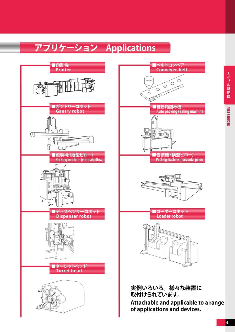
エイブル 減 速 機 は 豊 富 なバリエーションでお 客 様 の 要 望 にお 応 え Nidec Shimpo has a lineup with a lot of product variation; Able reducers 同 芯 軸 タイプ ABLE Reducer 静 音 高 精 度
|
|
|
- としはる あると
- 9 years ago
- Views:
Transcription
1 Coaxial shaft type VRS VRS series VRT VRT series VRSF VRSF series VRG VRG series

2 エイブル 減 速 機 は 豊 富 なバリエーションでお 客 様 の 要 望 にお 応 え Nidec Shimpo has a lineup with a lot of product variation; Able reducers 同 芯 軸 タイプ ABLE Reducer 静 音 高 精 度 コンパクトサーボモータ 市 場 をリードするエイブル 減 速 機 各 種 シリーズでお 客 様 の 要 望 にお 応 えします 1 静 音 高 剛 性 大 容 量 タイプ VRS series VRT series VRG series Quiet, high rigidity, big capacity Type 半 導 体 装 置 工 作 機 械 など 高 精 度 をお 求 めのお 客 様 に バックラッシ サイズ 静 音 高 剛 性 大 容 量 フランジ 出 力 タイプ 静 音 高 剛 性 精 密 タイプ Backlash : 3arcmin Frame size : 060B 075B B 1B 180B 2B 2B 減 速 比 Ratio : 1 段 Single 1/3, 1/4, 1/5, 1/6, 1/7, 1/8, 1/, 1/ 2 段 Double 1/15, 1/16, 1/, 1/25, 1/28, 1/, 1/ 1/, 1/45, 1/, 1/60, 1/, 1/80, 1/0, 1/ Quiet, high rigidity, big capacity, flange output Type 半 導 体 装 置 工 作 機 械 など 高 精 度 をお 求 めのお 客 様 に 44 バックラッシ Backlash : 3arcmin サイズ Frame size : B 1B 0B 255B 285B 減 速 比 Ratio : 1 段 Single 1/4, 1/5, 1/6, 1/7, 1/8, 1/, 1/ 2 段 Double 1/16, 1/, 1/25, 1/28, 1/, 1/ 1/45, 1/, 1/60, 1/, 1/80, 1/0, 1/ Quiet, high rigidity, precision Type フレームサイズが1B 以 上 は 減 速 比 が 変 わります Reduction ratios are different for frame size 1B or larger. 高 精 度 静 音 軽 量 標 準 タイプ Highprecision, quiet, light weight, standard type VRSF series For those customers who seek for high precision for Semiconductor and industrial application For those customers who seek for high precision for Semiconductor and industrial application 減 速 比 Ratio : 1 段 Single 1/3, 1/5, 1/ 2 段 Double 1/15, 1/, 1/25, 1/, 1/45, 1/81 バックラッシ サイズ 減 速 比 Ratio : 1 段 Single 1/3.67, 1/4, 1/5, 1/7, 1/, 1/ 2 段 Double 1/11, 1/15.4, 1/, 1/21, 1/25, 1/33, 1/ 1/, 1/45, 1/, 1/, 1/81, 1/ 受 注 生 産 品 : Madetoorder products サイズ047の2 段 のみ 5arcmin Only for frame size 047 of double reduction, 5 arcmin バックラッシ Backlash : 3arcmin 5arcmin arcmin 15arcmin サイズ Frame size : B C D E 半 導 体 装 置 工 作 機 械 など 高 精 度 をお 求 めのお 客 様 に Backlash : 1arcmin (madetoorder products), 3arcmin Frame size : B60P C0/C0P D1 E1 INDEX 8 特 徴 Features 機 種 型 式 記 号 Model number 性 能 一 覧 11 Performance table 寸 法 一 覧 1 Dimensions 寸 法 一 覧 (アダプタ) 32 Dimensions (Adapter) 効 率 特 性 3 Efficiency 特 徴 45 Features 機 種 型 式 記 号 46 Model number 性 能 一 覧 47 Performance table 寸 法 一 覧 56 Dimensions 寸 法 一 覧 (アダプタ) 6 Dimensions (Adapter) 特 性 76 Characteristics ガントリー 包 装 機 械 など 軽 量 コンパクトをご 要 求 されるお 客 様 に 78 For those customers who seek for light weight and compact size for gantry and packaging application B 枠 のみ For those customers who seek for high precision for Semiconductor and industrial application 特 徴 7 Features 種 類 80 Kind 減 速 比 枠 番 81 Reduction ratio/frame size 機 種 型 式 記 号 Model number 性 能 一 覧 83 8 Performance table 寸 法 一 覧 85 1 Dimensions モータマッチング 表 86 Motor matching table 作 動 原 理 6 Operating principle 技 術 資 料 7 Technical data 特 徴 1 Features 機 種 型 式 記 号 2 Model number 減 速 比 枠 番 3 Reduction ratio/frame size 性 能 一 覧 4 Performance table 寸 法 一 覧 8 Dimensions 特 性 114 Characteristics 効 率 特 性 116 Efficiency 作 動 原 理 1 Operating principle 減 速 機 選 定 手 順 121 Reducer selection procedure 主 軸 受 寿 命 122 Main bearing life

3 します to meet customer's requirement. Coaxial shaft ABLE Reducer Able reducer at the forefront of the compact servo motor market as Quiet, High precision There are various series to meet customer's requirement. 小 型 タイプ VRT series VRT042 小 型 タイプ Compact Type 業 界 最 小 クラスをラインアップ World smallest class reducers バックラッシ Backlash : 3arcmin 5arcmin サイズ Frame size : 042 減 速 比 Ratio : 1 段 Single 1/4, 1/5, 1/6, 1/7, 1/8, 1/, 1/ 2 段 Double 1/16, 1/, 1/25, 1/28, 1/, 1/ 1/45, 1/, 1/60, 1/, 1/80, 1/0, 1/ INDEX 123 特 徴 123 Features 機 種 型 式 記 号 123 Model number 性 能 一 覧 124 Performance table 寸 法 一 覧 125 Dimensions Compact Type VRB series VRB042 業 界 最 小 クラスをラインアップ World smallest class reducers バックラッシ Backlash : 3arcmin 5arcmin サイズ Frame size : 042 減 速 比 Ratio : 1 段 Single 1/3, 1/4, 1/5, 1/6, 1/7, 1/8, 1/, 1/ 2 段 Double 1/15, 1/16, 1/, 1/25, 1/28, 1/, 1/ 1/, 1/45, 1/, 1/60, 1/, 1/80, 1/0, 1/ 127 特 徴 127 Features 機 種 型 式 記 号 127 Model number 性 能 一 覧 128 Performance table 寸 法 一 覧 12 Dimensions 小 型 タイプ Compact Type VRL series VRL0B 業 界 最 小 クラスをラインアップ World smallest class reducers バックラッシ Backlash : 5arcmin 7arcmin サイズ Frame size : 0B 減 速 比 Ratio : 1 段 Single 1/3, 1/4, 1/5, 1/6, 1/7, 1/8, 1/, 1/ 2 段 Double 1/15, 1/16, 1/, 1/25, 1/28, 1/, 1/ 1/, 1/45, 1/, 1/60, 1/, 1/80, 1/0, 1/ 131 特 徴 131 Features 機 種 型 式 記 号 131 Model number 性 能 一 覧 132 Performance table 寸 法 一 覧 133 Dimensions 特 性 134 Characteristics 選 定 ツール Selection Tool アプリケーション Applications 取 付 方 法 Installation 安 全 上 のご 注 意 Safety Precautions サーボモータメーカ 一 覧 Servo Motor Manufacturer List ネットワーク Network


4 エイブル 減 速 機 選 定 ツール Servo Reducer Selection Tool STEP 1 画 面 中 央 にある 減 速 機 選 定 ツール のバナーをクリック Click the "Servo Reducer Selection tool" STEP 3 1 取 付 モータから 減 速 機 を 選 定 取 付 モータと 減 速 機 を 選 択 する Make a selection from the motor list Select the motor and the reducer 取 付 けるサーボモータメーカとモータ 型 式 を 選 択 します 取 付 ける 減 速 機 のシリーズと 減 速 比 を 選 択 します STEP 2 下 記 の 画 面 が 立 ち 上 がります 選 定 方 法 は 以 下 の 4 種 類 があります 1 取 付 モータから 減 速 機 を 選 定 2 負 荷 条 件 から 減 速 機 を 選 定 3アプリケーション 検 索 4 型 式 検 索 NEW! The screen below appears There are 4 ways to select the reducer 1Make a selection from the motor list 2Make a selection from load condition 3Application selection 4Search reducer models NEW! ここでは カタログをダウンロードできます 選 択 が 終 わったら ボタンをクリックします Select the servo motor maker and model name Select the reducer type and reduction ration * Here, you can download the catalogue After making a selection click "Back" or "Next" STEP 3 2 負 荷 条 件 から 減 速 機 を 選 定 減 速 機 のシリーズを 選 択 する Make a selection from load condition Select the reducer type STEP 3 3アプリケーション 検 索 アプリケーションを 選 択 する Application selection Select the application 3

5 エイブル 減 速 機 を 4 種 類 の 方 法 から 簡 単 選 定 するよ! Select the Able reducers in 4 ways STEP 4 減 速 機 サイズを 選 択 する Select the reducer size 注 ) EVRG および STH シリーズは 掲 載 されておりません EVRG and STH series are not listed. はじめちゃん 次 ページへ to Next page モータ 型 式 によっては 選 択 できるサイズとできないサイズがあります 減 速 機 サイズを 選 択 して をクリックします STEP 4 負 荷 条 件 を 入 力 する 運 転 パターン 数 減 速 比 ラジアル 回 転 数 スラスト 荷 重 荷 重 距 離 係 数 を 入 力 します Depending on the motor model, certain sizes cannot be selected Select the reducer size and click "Back" or "Next" 次 ページへ to Next page Input load condition input operaion cycle, reduction ration radial, rpm, thrust load, load distance, fomula STEP 5 減 速 機 シリーズ 減 速 比 を 選 択 する 必 要 に 応 じて 荷 重 距 離 係 数 を 入 力 します Select the reducer model and reduction ratio Input load distance and fomula if needed 次 ページへ to Next page STEP 4 アプリケーションの 運 転 条 件 を 入 力 する Input operation cycle of the application 次 ページへ to Next page STEP 3 4 型 式 検 索 Search for the model number 4

6 エイブル 減 速 機 選 定 ツール Servo Reducer Selection Tool 1 取 付 モータから 減 速 機 を 選 定 Make a selection from the motor list 2 負 荷 条 件 から 減 速 機 を 選 定 Make a selection from load condition 3アプリケーション 検 索 Application selection 減 速 機 サイズを 選 択 する Select the reducer size STEP STEP STEP STEP This is just one example of how to utilize our Servo Reducer Selection Tool We will keep making the improvment in its function of the Servo Reducer Selection Tool with the aim of making the best user friendly tool モータメーカ 型 式 を 選 択 する Select the motor make and the model name 条 件 によっては 選 択 できるサイズと 選 択 できないサイズがあります Depending on the condition, certain sizes cannot be chosen or can be chosen 負 荷 条 件 出 力 可 能 なモータが 選 択 できます The motor which can provide load condition can be selected 4 型 式 検 索 Search for the model number 外 形 寸 法 図 CADデータのダウンロード Download dimensions, CAD file 減 速 機 の 選 定 結 果 The result of the reducer selection 選 定 完 了 Finish selection PDF DXF IGS STP の 型 式 でダウンロードできます PDF, DXF, IGS, STP format data can be downloaded. 仕 様 表 のダウンロード Download specification 選 定 した 型 式 について 仕 様 表 が ダウンロードできるようになりました ( 登 録 不 要 ) The specification sheet of the selected reducer can be downloaded. (No registration required) 減 速 機 の 選 定 結 果 には 減 速 機 型 番 減 速 機 仕 様 取 付 モータ 仕 様 が 表 示 されます また 仕 様 表 外 形 寸 法 図 (PDF 2D 3D) がダウンロードできます The result page shows the model number of the reducer and the specification of the reducer and the motor. The specification sheet, and dimension of the reducer (PDF, CAD drawing in DXF, IGS, and STP) can be downloaded from the same page. 5

7 6
8 MEMO 7
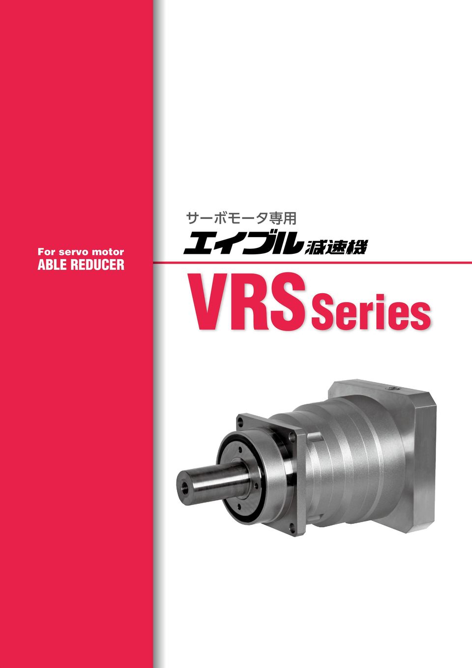
9 For servo motor VRSSeries
10 VRS Coaxial shaft series 特 徴 Features VRS series 高 精 度 バックラッシは3 分 以 下 精 密 な 位 置 決 めに 威 力 を 発 揮 High precision Standard backlash is 3 arcmin, ideal for precision control. 高 剛 性 高 トルク 総 ころ 形 軸 受 を 採 用 し 剛 性 トルクを 大 幅 にアップ High rigidity & torque High rigidity & high torque were achived by uncaged needle roller bearings. 高 荷 重 容 量 主 軸 受 にテーパローラベアリングを 採 用 し 高 荷 重 容 量 を 実 現 High load capacity Adopting taper roller bearing for the main output shaft to increase radial and axial load. アダプタ ブッシング 方 式 世 界 中 のモータに 取 付 可 能 Adapterbushing connection Can be attached to any motor all over the world. グリース 漏 れ 無 し 高 粘 度 で 分 離 しにくいグリースを 採 用 し 万 全 の 漏 油 対 策 を 実 施 No grease leakage Perfect solution using high viscosity antiseparation grease. メンテナンスフリー 製 品 寿 命 内 はグリース 交 換 不 要 取 付 姿 勢 も 自 由 自 在 Maintenancefree No need to replace the grease for the life of the unit. Can be attached in any position. VR

11 機 種 型 式 記 号 Model number Coaxial shaft VRS series VRS series バックラッシ Backlash マウントコード( 1) Mount code( 1) 3 3 分 3arcmin 出 力 方 式 Output style K S 出 力 軸 キー 付 き Shaft with key 出 力 軸 キー 無 し Smooth shaft 減 速 比 Ratio 1 段 Single 2 段 Double : : バージョン Version B サイズ Frame size シリーズ 名 Series name VRSシリーズ VRS Series エイブル 減 速 機 の 呼 称 Model name for ABLE reducer 1 マウントコード 1 Mount code マウントコードは 取 付 けモータによって 決 まります ホームページ 上 の 選 定 ツールにて 確 認 できます 不 明 な 場 合 はお 問 い 合 わせください モータとの 締 付 け 方 式 について モータ 軸 は キー 溝 なし ストレート 軸 での 取 付 けと なります モータ 軸 がキー 溝 付 の 場 合 は キーを 取 外 して 取 付 けください モータ 軸 がDカットの 場 合 はお 問 い 合 わせください Mount code varies depending on the motor. Please refer to reducer selection tool or contact us for more information. Mounting style to the motor Motor output shaft is the smooth shaft without keyway. If the motor output shaft is with the keyway, remove the key from the shaft. If the motor output shaft has D shape cut, contact us. VR

12 VRS Coaxial shaft series 性 能 一 覧 Performance table VRS060B サイズ Frame size 段 数 Stage 減 速 比 Ratio 許 容 平 均 トルク Nominal output torque 許 容 最 大 トルク output torque 非 常 時 最 大 トルク Emergency stop torque 許 容 平 均 入 力 回 転 数 Nominal input speed 許 容 最 高 入 力 回 転 数 input speed 許 容 ラジアル 荷 重 Permitted radial load 許 容 スラスト 荷 重 Permitted axial load 1 段 Single 060B 2 段 Double サイズ Frame size 段 数 Stage 減 速 比 Ratio 許 容 最 大 ラジアル 荷 重 radial load 許 容 最 大 スラスト 荷 重 axial load 重 量 Weight 慣 性 モーメント Moment of inertia 慣 性 モーメント Moment of inertia 慣 性 モーメント Moment of inertia 1 段 Single 060B 2 段 Double 1 許 容 平 均 入 力 回 転 数 の 時 寿 命 000 時 間 となる 値 2 起 動 停 止 時 に 許 容 する 最 大 値 3 衝 撃 等 が 作 用 した 時 に 許 容 する 最 大 値 ( 頻 度 は0 回 まで) 4 運 転 中 の 平 均 入 力 回 転 数 の 許 容 最 大 値 5 連 続 運 転 ではない 条 件 下 での 許 容 最 高 入 力 回 転 数 6 許 容 平 均 入 力 回 転 数 の 時 寿 命 000 時 間 となる 値 ( 軸 中 央 に 作 用 スラスト 荷 重 が 0 のとき) 7 許 容 平 均 入 力 回 転 数 の 時 寿 命 000 時 間 となる 値 ( 軸 芯 に 作 用 ラジアル 荷 重 が 0 のとき) 8 ラジアル 荷 重 の 許 容 最 大 値 スラスト 荷 重 の 許 容 最 大 値 減 速 比 及 び 入 力 軸 寸 法 により 若 干 異 なります 1 With nominal input speed, service life is,000 hours. 2 The maximum torque when starting and stopping. 3 The maximum torque when it receives shock. (up to 1,000 times) 4 The maximum average input speed. 5 The maximum momentary input speed. 6 With this load and nominal input speed, service life will be,000 hours. (Applied to the output shaft center, at axial load 0) 7 With this load and nominal input speed, service life will be,000 hours. (Applied to the output side bearing, at radial load 0) 8 The maximum radial load the reducer can accept. The maximum axial load the reducer can accept. The weight may vary slightly model to model. 11 VR
 4 運 転 中 の 平 均 入 力 回 転 数 の 許 容 最 大 値 5 連 続 運 転 ではない 条 件 下 での 許 容 最 高 入 力 回 転 数 6 許 容 平 均 入 力 回 転 数 の 時 寿 命")
13 性 能 一 覧 Performance table Coaxial shaft VRS series VRS075B サイズ Frame size 段 数 Stage 減 速 比 Ratio 許 容 平 均 トルク Nominal output torque 許 容 最 大 トルク output torque 非 常 時 最 大 トルク Emergency stop torque 許 容 平 均 入 力 回 転 数 Nominal input speed 許 容 最 高 入 力 回 転 数 input speed 許 容 ラジアル 荷 重 Permitted radial load 許 容 スラスト 荷 重 Permitted axial load 1 段 Single 075B 2 段 Double サイズ Frame size 段 数 Stage 減 速 比 Ratio 許 容 最 大 ラジアル 荷 重 radial load 許 容 最 大 スラスト 荷 重 axial load 重 量 Weight 慣 性 モーメント Moment of inertia 慣 性 モーメント Moment of inertia 慣 性 モーメント Moment of inertia 慣 性 モーメント Moment of inertia 1 段 Single 075B 2 段 Double 1 許 容 平 均 入 力 回 転 数 の 時 寿 命 000 時 間 となる 値 2 起 動 停 止 時 に 許 容 する 最 大 値 3 衝 撃 等 が 作 用 した 時 に 許 容 する 最 大 値 ( 頻 度 は 0 回 まで) 4 運 転 中 の 平 均 入 力 回 転 数 の 許 容 最 大 値 5 連 続 運 転 ではない 条 件 下 での 許 容 最 高 入 力 回 転 数 6 許 容 平 均 入 力 回 転 数 の 時 寿 命 000 時 間 となる 値 ( 軸 中 央 に 作 用 スラスト 荷 重 が 0 のとき) 7 許 容 平 均 入 力 回 転 数 の 時 寿 命 000 時 間 となる 値 ( 軸 芯 に 作 用 ラジアル 荷 重 が 0 のとき) 8 ラジアル 荷 重 の 許 容 最 大 値 スラスト 荷 重 の 許 容 最 大 値 減 速 比 及 び 入 力 軸 寸 法 により 若 干 異 なります 1 With nominal input speed, service life is,000 hours. 2 The maximum torque when starting and stopping. 3 The maximum torque when it receives shock. (up to 1,000 times) 4 The maximum average input speed. 5 The maximum momentary input speed. 6 With this load and nominal input speed, service life will be,000 hours. (Applied to the output shaft center, at axial load 0) 7 With this load and nominal input speed, service life will be,000 hours. (Applied to the output side bearing, at radial load 0) 8 The maximum radial load the reducer can accept. The maximum axial load the reducer can accept. The weight may vary slightly model to model. VR 12
 4 運 転 中 の 平 均 入 力 回 転 数 の 許 容 最 大 値 5 連 続 運 転 ではない 条 件 下 での 許 容 最 高 入 力 回")
14 VRS Coaxial shaft series 性 能 一 覧 Performance table VRSB サイズ Frame size 段 数 Stage 減 速 比 Ratio 許 容 平 均 トルク Nominal output torque 許 容 最 大 トルク output torque 非 常 時 最 大 トルク Emergency stop torque 許 容 平 均 入 力 回 転 数 Nominal input speed 許 容 最 高 入 力 回 転 数 input speed 許 容 ラジアル 荷 重 Permitted radial load 許 容 スラスト 荷 重 Permitted axial load 1 段 Single B 2 段 Double サイズ Frame size 段 数 Stage 減 速 比 Ratio 許 容 最 大 ラジアル 荷 重 radial load 許 容 最 大 スラスト 荷 重 axial load 重 量 Weight 慣 性 モーメント Moment of inertia 慣 性 モーメント Moment of inertia 慣 性 モーメント Moment of inertia 慣 性 モーメント Moment of inertia 1 段 Single B 2 段 Double 1 許 容 平 均 入 力 回 転 数 の 時 寿 命 000 時 間 となる 値 2 起 動 停 止 時 に 許 容 する 最 大 値 3 衝 撃 等 が 作 用 した 時 に 許 容 する 最 大 値 ( 頻 度 は 0 回 まで) 4 運 転 中 の 平 均 入 力 回 転 数 の 許 容 最 大 値 5 連 続 運 転 ではない 条 件 下 での 許 容 最 高 入 力 回 転 数 6 許 容 平 均 入 力 回 転 数 の 時 寿 命 000 時 間 となる 値 ( 軸 中 央 に 作 用 スラスト 荷 重 が 0 のとき) 7 許 容 平 均 入 力 回 転 数 の 時 寿 命 000 時 間 となる 値 ( 軸 芯 に 作 用 ラジアル 荷 重 が 0 のとき) 8 ラジアル 荷 重 の 許 容 最 大 値 スラスト 荷 重 の 許 容 最 大 値 減 速 比 及 び 入 力 軸 寸 法 により 若 干 異 なります 1 With nominal input speed, service life is,000 hours. 2 The maximum torque when starting and stopping. 3 The maximum torque when it receives shock. (up to 1,000 times) 4 The maximum average input speed. 5 The maximum momentary input speed. 6 With this load and nominal input speed, service life will be,000 hours. (Applied to the output shaft center, at axial load 0) 7 With this load and nominal input speed, service life will be,000 hours. (Applied to the output side bearing, at radial load 0) 8 The maximum radial load the reducer can accept. The maximum axial load the reducer can accept. The weight may vary slightly model to model. 13 VR
 4 運 転 中 の 平 均 入 力 回 転 数 の 許 容 最 大 値 5 連 続 運 転 ではない 条 件 下 での 許 容 最 高 入 力 回 転 数 6 許 容")
15 性 能 一 覧 Performance table Coaxial shaft VRS series VRS1B サイズ Frame size 段 数 Stage 減 速 比 Ratio 許 容 平 均 トルク Nominal output torque 許 容 最 大 トルク output torque 非 常 時 最 大 トルク Emergency stop torque 許 容 平 均 入 力 回 転 数 Nominal input speed 許 容 最 高 入 力 回 転 数 input speed 許 容 ラジアル 荷 重 Permitted radial load 許 容 スラスト 荷 重 Permitted axial load 1 段 Single 1B 2 段 Double サイズ Frame size 段 数 Stage 減 速 比 Ratio 許 容 最 大 ラジアル 荷 重 radial load 許 容 最 大 スラスト 荷 重 axial load 重 量 Weight 慣 性 モーメント Moment of inertia 慣 性 モーメント Moment of inertia 慣 性 モーメント Moment of inertia 慣 性 モーメント Moment of inertia 1 段 Single 1B 2 段 Double 1 許 容 平 均 入 力 回 転 数 の 時 寿 命 000 時 間 となる 値 2 起 動 停 止 時 に 許 容 する 最 大 値 3 衝 撃 等 が 作 用 した 時 に 許 容 する 最 大 値 ( 頻 度 は 0 回 まで) 4 運 転 中 の 平 均 入 力 回 転 数 の 許 容 最 大 値 5 連 続 運 転 ではない 条 件 下 での 許 容 最 高 入 力 回 転 数 6 許 容 平 均 入 力 回 転 数 の 時 寿 命 000 時 間 となる 値 ( 軸 中 央 に 作 用 スラスト 荷 重 が 0 のとき) 7 許 容 平 均 入 力 回 転 数 の 時 寿 命 000 時 間 となる 値 ( 軸 芯 に 作 用 ラジアル 荷 重 が 0 のとき) 8 ラジアル 荷 重 の 許 容 最 大 値 スラスト 荷 重 の 許 容 最 大 値 減 速 比 及 び 入 力 軸 寸 法 により 若 干 異 なります 1 With nominal input speed, service life is,000 hours. 2 The maximum torque when starting and stopping. 3 The maximum torque when it receives shock. (up to 1,000 times) 4 The maximum average input speed. 5 The maximum momentary input speed. 6 With this load and nominal input speed, service life will be,000 hours. (Applied to the output shaft center, at axial load 0) 7 With this load and nominal input speed, service life will be,000 hours. (Applied to the output side bearing, at radial load 0) 8 The maximum radial load the reducer can accept. The maximum axial load the reducer can accept. The weight may vary slightly model to model. VR 14
 4 運 転 中 の 平 均 入 力 回 転 数 の 許 容 最 大 値 5 連 続 運 転 ではない 条 件 下 での 許 容 最 高 入 力 回 転 数 6 許")
16 VRS Coaxial shaft series 性 能 一 覧 Performance table VRS180B サイズ Frame size 段 数 Stage 減 速 比 Ratio 許 容 平 均 トルク Nominal output torque 許 容 最 大 トルク output torque 非 常 時 最 大 トルク Emergency stop torque 許 容 平 均 入 力 回 転 数 Nominal input speed 許 容 最 高 入 力 回 転 数 input speed 許 容 ラジアル 荷 重 Permitted radial load 許 容 スラスト 荷 重 Permitted axial load 1 段 Single 180B 2 段 Double サイズ Frame size 段 数 Stage 減 速 比 Ratio 許 容 最 大 ラジアル 荷 重 radial load 許 容 最 大 スラスト 荷 重 axial load 重 量 Weight 慣 性 モーメント Moment of inertia 慣 性 モーメント Moment of inertia 慣 性 モーメント Moment of inertia 慣 性 モーメント Moment of inertia 1 段 Single 180B 2 段 Double 1 許 容 平 均 入 力 回 転 数 の 時 寿 命 000 時 間 となる 値 2 起 動 停 止 時 に 許 容 する 最 大 値 3 衝 撃 等 が 作 用 した 時 に 許 容 する 最 大 値 ( 頻 度 は 0 回 まで) 4 運 転 中 の 平 均 入 力 回 転 数 の 許 容 最 大 値 5 連 続 運 転 ではない 条 件 下 での 許 容 最 高 入 力 回 転 数 6 許 容 平 均 入 力 回 転 数 の 時 寿 命 000 時 間 となる 値 ( 軸 中 央 に 作 用 スラスト 荷 重 が 0 のとき) 7 許 容 平 均 入 力 回 転 数 の 時 寿 命 000 時 間 となる 値 ( 軸 芯 に 作 用 ラジアル 荷 重 が 0 のとき) 8 ラジアル 荷 重 の 許 容 最 大 値 スラスト 荷 重 の 許 容 最 大 値 減 速 比 及 び 入 力 軸 寸 法 により 若 干 異 なります 1 With nominal input speed, service life is,000 hours. 2 The maximum torque when starting and stopping. 3 The maximum torque when it receives shock. (up to 1,000 times) 4 The maximum average input speed. 5 The maximum momentary input speed. 6 With this load and nominal input speed, service life will be,000 hours. (Applied to the output shaft center, at axial load 0) 7 With this load and nominal input speed, service life will be,000 hours. (Applied to the output side bearing, at radial load 0) 8 The maximum radial load the reducer can accept. The maximum axial load the reducer can accept. The weight may vary slightly model to model. 15 VR
 4 運 転 中 の 平 均 入 力 回 転 数 の 許 容 最 大 値 5 連 続 運 転 ではない 条 件 下 での 許 容 最 高 入 力 回")
17 性 能 一 覧 Performance table Coaxial shaft VRS series VRS2B サイズ Frame size 段 数 Stage 減 速 比 Ratio 許 容 平 均 トルク Nominal output torque 許 容 最 大 トルク output torque 非 常 時 最 大 トルク Emergency stop torque 許 容 平 均 入 力 回 転 数 Nominal input speed 許 容 最 高 入 力 回 転 数 input speed 許 容 ラジアル 荷 重 Permitted radial load 許 容 スラスト 荷 重 Permitted axial load 1 段 Single 2B 2 段 Double サイズ Frame size 段 数 Stage 減 速 比 Ratio 許 容 最 大 ラジアル 荷 重 radial load 許 容 最 大 スラスト 荷 重 axial load 重 量 Weight 慣 性 モーメント Moment of inertia 慣 性 モーメント Moment of inertia 慣 性 モーメント Moment of inertia 1 段 Single 2B 2 段 Double 1 許 容 平 均 入 力 回 転 数 の 時 寿 命 000 時 間 となる 値 2 起 動 停 止 時 に 許 容 する 最 大 値 3 衝 撃 等 が 作 用 した 時 に 許 容 する 最 大 値 ( 頻 度 は 0 回 まで) 4 運 転 中 の 平 均 入 力 回 転 数 の 許 容 最 大 値 5 連 続 運 転 ではない 条 件 下 での 許 容 最 高 入 力 回 転 数 6 許 容 平 均 入 力 回 転 数 の 時 寿 命 000 時 間 となる 値 ( 軸 中 央 に 作 用 スラスト 荷 重 が 0 のとき) 7 許 容 平 均 入 力 回 転 数 の 時 寿 命 000 時 間 となる 値 ( 軸 芯 に 作 用 ラジアル 荷 重 が 0 のとき) 8 ラジアル 荷 重 の 許 容 最 大 値 スラスト 荷 重 の 許 容 最 大 値 減 速 比 及 び 入 力 軸 寸 法 により 若 干 異 なります 1 With nominal input speed, service life is,000 hours. 2 The maximum torque when starting and stopping. 3 The maximum torque when it receives shock. (up to 1,000 times) 4 The maximum average input speed. 5 The maximum momentary input speed. 6 With this load and nominal input speed, service life will be,000 hours. (Applied to the output shaft center, at axial load 0) 7 With this load and nominal input speed, service life will be,000 hours. (Applied to the output side bearing, at radial load 0) 8 The maximum radial load the reducer can accept. The maximum axial load the reducer can accept. The weight may vary slightly model to model. VR 16
 4 運 転 中 の 平 均 入 力 回 転 数 の 許 容 最 大 値 5 連 続 運 転 ではない 条 件 下 での 許 容 最 高 入 力 回 転 数 6 許 容 平 均 入 力 回 転 数 の 時 寿 命")
18 VRS Coaxial shaft series 性 能 一 覧 Performance table VRS2B サイズ Frame size 段 数 Stage 減 速 比 Ratio 許 容 平 均 トルク Nominal output torque 許 容 最 大 トルク output torque 非 常 時 最 大 トルク Emergency stop torque 許 容 平 均 入 力 回 転 数 Nominal input speed 許 容 最 高 入 力 回 転 数 input speed 許 容 ラジアル 荷 重 Permitted radial load 許 容 スラスト 荷 重 Permitted axial load 1 段 Single 2B 2 段 Double サイズ Frame size 段 数 Stage 減 速 比 Ratio 許 容 最 大 ラジアル 荷 重 radial load 許 容 最 大 スラスト 荷 重 axial load 重 量 Weight 慣 性 モーメント Moment of inertia 慣 性 モーメント Moment of inertia 1 段 Single 2B 2 段 Double 1 許 容 平 均 入 力 回 転 数 の 時 寿 命 000 時 間 となる 値 2 起 動 停 止 時 に 許 容 する 最 大 値 3 衝 撃 等 が 作 用 した 時 に 許 容 する 最 大 値 ( 頻 度 は 0 回 まで) 4 運 転 中 の 平 均 入 力 回 転 数 の 許 容 最 大 値 5 連 続 運 転 ではない 条 件 下 での 許 容 最 高 入 力 回 転 数 6 許 容 平 均 入 力 回 転 数 の 時 寿 命 000 時 間 となる 値 ( 軸 中 央 に 作 用 スラスト 荷 重 が 0 のとき) 7 許 容 平 均 入 力 回 転 数 の 時 寿 命 000 時 間 となる 値 ( 軸 芯 に 作 用 ラジアル 荷 重 が 0 のとき) 8 ラジアル 荷 重 の 許 容 最 大 値 スラスト 荷 重 の 許 容 最 大 値 減 速 比 及 び 入 力 軸 寸 法 により 若 干 異 なります 1 With nominal input speed, service life is,000 hours. 2 The maximum torque when starting and stopping. 3 The maximum torque when it receives shock. (up to 1,000 times) 4 The maximum average input speed. 5 The maximum momentary input speed. 6 With this load and nominal input speed, service life will be,000 hours. (Applied to the output shaft center, at axial load 0) 7 With this load and nominal input speed, service life will be,000 hours. (Applied to the output side bearing, at radial load 0) 8 The maximum radial load the reducer can accept. The maximum axial load the reducer can accept. The weight may vary slightly model to model. 17 VR
 4 運 転 中 の 平 均 入 力 回 転 数 の 許 容 最 大 値 5 連 続 運 転 ではない 条 件 下 での 許 容 最 高 入 力 回 転 数 6 許 容 平 均 入 力 回 転 数 の 時 寿 命 000 時 間 となる 値 ( 軸 中 央 に 作 用 スラスト")
19 Coaxial shaft VRS series MEMO VR 18

20 VRS Coaxial shaft series 寸 法 一 覧 Dimensions VRS060B 1 段 1stage 入 力 軸 内 径 φ8 入 力 軸 内 径 φ14 入 力 軸 内 径 φ1 1 取 付 けモータにより 変 化 する 場 合 があります 2 モータ 軸 径 が 入 力 軸 径 と 異 なる 場 合 は ブッシングが 挿 入 されます 1 Length will vary depending on motor. 2 Bushing will be inserted to adapt to motor shaft. 1 VR

21 寸 法 一 覧 Dimensions Coaxial shaft VRS series VRS060B 2 段 2stage 入 力 軸 内 径 φ8 入 力 軸 内 径 φ14 1 取 付 けモータにより 変 化 する 場 合 があります 2 モータ 軸 径 が 入 力 軸 径 と 異 なる 場 合 は ブッシングが 挿 入 されます 1 Length will vary depending on motor. 2 Bushing will be inserted to adapt to motor shaft. VR
22 VRS Coaxial shaft series 寸 法 一 覧 Dimensions VRS075B 1 段 1stage 入 力 軸 内 径 φ14 入 力 軸 内 径 φ1 入 力 軸 内 径 φ28 1 取 付 けモータにより 変 化 する 場 合 があります 2 モータ 軸 径 が 入 力 軸 径 と 異 なる 場 合 は ブッシングが 挿 入 されます 1 Length will vary depending on motor. 2 Bushing will be inserted to adapt to motor shaft. 21 VR
23 寸 法 一 覧 Dimensions Coaxial shaft VRS series VRS075B 2 段 2stage 入 力 軸 内 径 φ8 入 力 軸 内 径 φ14 入 力 軸 内 径 φ1 1 取 付 けモータにより 変 化 する 場 合 があります 2 モータ 軸 径 が 入 力 軸 径 と 異 なる 場 合 は ブッシングが 挿 入 されます 1 Length will vary depending on motor. 2 Bushing will be inserted to adapt to motor shaft. VR 22
24 VRS Coaxial shaft series 寸 法 一 覧 Dimensions VRSB 1 段 1stage 入 力 軸 内 径 φ1 入 力 軸 内 径 φ28 入 力 軸 内 径 φ38 1 取 付 けモータにより 変 化 する 場 合 があります 2 モータ 軸 径 が 入 力 軸 径 と 異 なる 場 合 は ブッシングが 挿 入 されます 1 Length will vary depending on motor. 2 Bushing will be inserted to adapt to motor shaft. 23 VR
25 寸 法 一 覧 Dimensions Coaxial shaft VRS series VRSB 2 段 2stage 入 力 軸 内 径 φ14 入 力 軸 内 径 φ1 入 力 軸 内 径 φ28 1 取 付 けモータにより 変 化 する 場 合 があります 2 モータ 軸 径 が 入 力 軸 径 と 異 なる 場 合 は ブッシングが 挿 入 されます 1 Length will vary depending on motor. 2 Bushing will be inserted to adapt to motor shaft. VR 24
26 VRS Coaxial shaft series 寸 法 一 覧 Dimensions VRS1B 1 段 1stage 入 力 軸 内 径 φ28 入 力 軸 内 径 φ38 入 力 軸 内 径 φ48 1 取 付 けモータにより 変 化 する 場 合 があります 2 モータ 軸 径 が 入 力 軸 径 と 異 なる 場 合 は ブッシングが 挿 入 されます 1 Length will vary depending on motor. 2 Bushing will be inserted to adapt to motor shaft. 25 VR
27 寸 法 一 覧 Dimensions Coaxial shaft VRS series VRS1B 2 段 2stage 入 力 軸 内 径 φ1 入 力 軸 内 径 φ28 入 力 軸 内 径 φ38 1 取 付 けモータにより 変 化 する 場 合 があります 2 モータ 軸 径 が 入 力 軸 径 と 異 なる 場 合 は ブッシングが 挿 入 されます 1 Length will vary depending on motor. 2 Bushing will be inserted to adapt to motor shaft. VR 26
28 VRS Coaxial shaft series 寸 法 一 覧 Dimensions VRS180B 1 段 1stage 入 力 軸 内 径 φ38 入 力 軸 内 径 φ48 入 力 軸 内 径 φ65 1 取 付 けモータにより 変 化 する 場 合 があります 2 モータ 軸 径 が 入 力 軸 径 と 異 なる 場 合 は ブッシングが 挿 入 されます 1 Length will vary depending on motor. 2 Bushing will be inserted to adapt to motor shaft. 27 VR
29 寸 法 一 覧 Dimensions Coaxial shaft VRS series VRS180B 2 段 2stage 入 力 軸 内 径 φ28 入 力 軸 内 径 φ38 入 力 軸 内 径 φ48 1 取 付 けモータにより 変 化 する 場 合 があります 2 モータ 軸 径 が 入 力 軸 径 と 異 なる 場 合 は ブッシングが 挿 入 されます 1 Length will vary depending on motor. 2 Bushing will be inserted to adapt to motor shaft. VR 28
30 VRS Coaxial shaft series 寸 法 一 覧 Dimensions VRS2B 1 段 1stage 入 力 軸 内 径 φ48 入 力 軸 内 径 φ65 1 取 付 けモータにより 変 化 する 場 合 があります 2 モータ 軸 径 が 入 力 軸 径 と 異 なる 場 合 は ブッシングが 挿 入 されます 1 Length will vary depending on motor. 2 Bushing will be inserted to adapt to motor shaft. 2 VR
31 寸 法 一 覧 Dimensions Coaxial shaft VRS series VRS2B 2 段 2stage 入 力 軸 内 径 φ38 入 力 軸 内 径 φ48 1 取 付 けモータにより 変 化 する 場 合 があります 2 モータ 軸 径 が 入 力 軸 径 と 異 なる 場 合 は ブッシングが 挿 入 されます 1 Length will vary depending on motor. 2 Bushing will be inserted to adapt to motor shaft. VR
32 VRS Coaxial shaft series 寸 法 一 覧 Dimensions VRS2B 1 段 1stage 入 力 軸 内 径 φ65 VRS2B 2 段 2stage 入 力 軸 内 径 φ48 1 取 付 けモータにより 変 化 する 場 合 があります 2 モータ 軸 径 が 入 力 軸 径 と 異 なる 場 合 は ブッシングが 挿 入 されます 1 Length will vary depending on motor. 2 Bushing will be inserted to adapt to motor shaft. 31 VR
33 寸 法 一 覧 (アダプタ) Dimensions(Adapter) Coaxial shaft VRS series VRS060B 型 式 Model number **:アダプタ 記 号 1 段 Single 2 段 Double **:Adapter code 入 力 軸 内 径 入 力 軸 内 径 入 力 軸 内 径 1 1 段 減 速 : 1/3 ~ 1/ 2 段 減 速 : 1/15 ~ 1/ 2 モータ 軸 径 が 入 力 軸 径 と 異 なる 場 合 は ブッシングが 挿 入 されます 3 アダプタは 代 表 です 詳 細 については 選 定 ツールでご 確 認 ください 1 Single reduction : 1/3~1/, Double reduction : 1/15~1/. 2 Bushing will be inserted to adapt to motor shaft. 3 The adapter is only for example. Please select the suitable adapter in the selection tool in our web site. VR 32
34 VRS Coaxial shaft series 寸 法 一 覧 (アダプタ) Dimensions(Adapter) VRS075B 型 式 Model number **:アダプタ 記 号 1 段 Single 2 段 Double **:Adapter code 入 力 軸 内 径 入 力 軸 内 径 入 力 軸 内 径 入 力 軸 内 径 1 1 段 減 速 : 1/3 ~ 1/ 2 段 減 速 : 1/15 ~ 1/ 2 モータ 軸 径 が 入 力 軸 径 と 異 なる 場 合 は ブッシングが 挿 入 されます 3 アダプタは 代 表 です 詳 細 については 選 定 ツールでご 確 認 ください 1 Single reduction : 1/3~1/, Double reduction : 1/15~1/. 2 Bushing will be inserted to adapt to motor shaft. 3 The adapter is only for example. Please select the suitable adapter in the selection tool in our web site. 33 VR
35 寸 法 一 覧 (アダプタ) Dimensions(Adapter) Coaxial shaft VRS series VRSB 型 式 Model number **:アダプタ 記 号 1 段 Single 2 段 Double **:Adapter code 入 力 軸 内 径 入 力 軸 内 径 入 力 軸 内 径 入 力 軸 内 径 1 1 段 減 速 : 1/3 ~ 1/ 2 段 減 速 : 1/15 ~ 1/ 2 モータ 軸 径 が 入 力 軸 径 と 異 なる 場 合 は ブッシングが 挿 入 されます 3 アダプタは 代 表 です 詳 細 については 選 定 ツールでご 確 認 ください 1 Single reduction : 1/3~1/, Double reduction : 1/15~1/. 2 Bushing will be inserted to adapt to motor shaft. 3 The adapter is only for example. Please select the suitable adapter in the selection tool in our web site. VR 34
36 VRS Coaxial shaft series 寸 法 一 覧 (アダプタ) Dimensions(Adapter) VRS1B 型 式 Model number **:アダプタ 記 号 1 段 Single 2 段 Double **:Adapter code 入 力 軸 内 径 入 力 軸 内 径 入 力 軸 内 径 入 力 軸 内 径 1 1 段 減 速 : 1/3 ~ 1/ 2 段 減 速 : 1/15 ~ 1/ 2 モータ 軸 径 が 入 力 軸 径 と 異 なる 場 合 は ブッシングが 挿 入 されます 3 アダプタは 代 表 です 詳 細 については 選 定 ツールでご 確 認 ください 1 Single reduction : 1/3~1/, Double reduction : 1/15~1/. 2 Bushing will be inserted to adapt to motor shaft. 3 The adapter is only for example. Please select the suitable adapter in the selection tool in our web site. VR
37 寸 法 一 覧 (アダプタ) Dimensions(Adapter) Coaxial shaft VRS series VRS180B 型 式 Model number **:アダプタ 記 号 1 段 Single 2 段 Double **:Adapter code 入 力 軸 内 径 入 力 軸 内 径 入 力 軸 内 径 入 力 軸 内 径 1 1 段 減 速 : 1/3 ~ 1/ 2 段 減 速 : 1/15 ~ 1/ 2 モータ 軸 径 が 入 力 軸 径 と 異 なる 場 合 は ブッシングが 挿 入 されます 3 アダプタは 代 表 です 詳 細 については 選 定 ツールでご 確 認 ください 1 Single reduction : 1/3~1/, Double reduction : 1/15~1/. 2 Bushing will be inserted to adapt to motor shaft. 3 The adapter is only for example. Please select the suitable adapter in the selection tool in our web site. VR 36
38 VRS Coaxial shaft series 寸 法 一 覧 (アダプタ) Dimensions(Adapter) VRS2B 型 式 Model number **:アダプタ 記 号 1 段 Single 2 段 Double **:Adapter code 入 力 軸 内 径 入 力 軸 内 径 入 力 軸 内 径 1 1 段 減 速 : 1/3 ~ 1/ 2 段 減 速 : 1/15 ~ 1/ 2 モータ 軸 径 が 入 力 軸 径 と 異 なる 場 合 は ブッシングが 挿 入 されます 3 アダプタは 代 表 です 詳 細 については 選 定 ツールでご 確 認 ください 1 Single reduction : 1/3~1/, Double reduction : 1/15~1/. 2 Bushing will be inserted to adapt to motor shaft. 3 The adapter is only for example. Please select the suitable adapter in the selection tool in our web site. 37 VR
39 寸 法 一 覧 (アダプタ) Dimensions(Adapter) Coaxial shaft VRS series VRS2B 型 式 Model number **:アダプタ 記 号 1 段 Single 2 段 Double **:Adapter code 入 力 軸 内 径 入 力 軸 内 径 1 1 段 減 速 : 1/3 ~ 1/ 2 段 減 速 : 1/15 ~ 1/ 2 モータ 軸 径 が 入 力 軸 径 と 異 なる 場 合 は ブッシングが 挿 入 されます 3 アダプタは 代 表 です 詳 細 については 選 定 ツールでご 確 認 ください 1 Single reduction : 1/3~1/, Double reduction : 1/15~1/. 2 Bushing will be inserted to adapt to motor shaft. 3 The adapter is only for example. Please select the suitable adapter in the selection tool in our web site. VR 38
40 VRS Coaxial shaft series 効 率 特 性 Efficiency VRS060B 入 力 回 転 速 度 :3,000rpmの 時 Input speed:3,000rpm 効 率 [%] Efficiency 効 率 [%] Efficiency VRS060B (3 4) 入 力 トルク [Nm] Input torque VRS060B (5) 入 力 トルク [Nm] Input torque 効 率 [%] Efficiency 効 率 [%] Efficiency VRS060B (1545) 入 力 トルク [Nm] Input torque VRS060B () 入 力 トルク [Nm] Input torque VRS075B 入 力 回 転 速 度 :3,000rpmの 時 Input speed:3,000rpm 効 率 [%] Efficiency VRS075B (3 4) 入 力 トルク [Nm] Input torque 効 率 [%] Efficiency VRS075B (1545) 入 力 トルク [Nm] Input torque 効 率 [%] Efficiency VRS075B (5) 入 力 トルク [Nm] Input torque 効 率 [%] Efficiency VRS075B () 入 力 トルク [Nm] Input torque 周 囲 温 度 25 Ambient temperature 25 3 VR
41 効 率 特 性 Efficiency Coaxial shaft VRS series VRSB 入 力 回 転 速 度 :3,000rpmの 時 Input speed:3,000rpm 効 率 [%] Efficiency 効 率 [%] Efficiency VRSB (3 4) 入 力 トルク [Nm] Input torque VRSB (5) 入 力 トルク [Nm] Input torque 効 率 [%] Efficiency 効 率 [%] Efficiency VRSB (1545) 入 力 トルク [Nm] Input torque VRSB () 入 力 トルク [Nm] Input torque VRS1B 入 力 回 転 速 度 :2,000rpmの 時 Input speed:2,000rpm 効 率 [%] Efficiency VRS1B (3 4) 入 力 トルク [Nm] Input torque 効 率 [%] Efficiency VRS1B (1545) 入 力 トルク [Nm] Input torque 効 率 [%] Efficiency VRS1B (5) 入 力 トルク [Nm] Input torque 効 率 [%] Efficiency VRS1B () 入 力 トルク [Nm] Input torque 周 囲 温 度 25 Ambient temperature 25 VR
42 VRS Coaxial shaft series 効 率 特 性 Efficiency VRS180B 入 力 回 転 速 度 :1,0rpmの 時 Input speed:1,0rpm 効 率 [%] Efficiency 効 率 [%] Efficiency VRS180B (3 4) 入 力 トルク [Nm] Input torque VRS180B (5) 入 力 トルク [Nm] Input torque 効 率 [%] Efficiency 効 率 [%] Efficiency VRS180B (1545) 入 力 トルク [Nm] Input torque VRS180B () 入 力 トルク [Nm] Input torque VRS2B 入 力 回 転 速 度 :1,000rpmの 時 Input speed:1,000rpm 効 率 [%] Efficiency VRS2B (3 4) 入 力 トルク [Nm] Input torque 効 率 [%] Efficiency VRS2B (1545) 入 力 トルク [Nm] Input torque 効 率 [%] Efficiency VRS2B (5) 入 力 トルク [Nm] Input torque 効 率 [%] Efficiency VRS2B () 入 力 トルク [Nm] Input torque 周 囲 温 度 25 Ambient temperature VR
43 効 率 特 性 Efficiency Coaxial shaft VRS series VRS2B 入 力 回 転 速 度 :1,000rpmの 時 Input speed:1,000rpm 効 率 [%] Efficiency 効 率 [%] Efficiency VRS2B (3 4) 入 力 トルク [Nm] Input torque VRS2B (5) 入 力 トルク [Nm] Input torque 効 率 [%] Efficiency 効 率 [%] Efficiency VRS2B (1545) 入 力 トルク [Nm] Input torque VRS2B () 入 力 トルク [Nm] Input torque 周 囲 温 度 25 Ambient temperature 25 VR 42
44 VRS Coaxial shaft series MEMO 43 VR
45 For servo motor VRTSeries
46 VRT Coaxial shaft series 特 徴 Features VRT series 高 精 度 バックラッシは3 分 以 下 精 密 な 位 置 決 めに 威 力 を 発 揮 High precision Standard backlash is 3 arcmin, ideal for precision control. 高 剛 性 高 トルク 総 ころ 形 軸 受 を 採 用 し 剛 性 トルクを 大 幅 にアップ High rigidity & torque High rigidity & high torque were achived by uncaged needle roller bearings. 高 荷 重 容 量 主 軸 受 にテーパローラベアリングを 採 用 し 高 荷 重 容 量 を 実 現 サイズ はボールベアリングを 採 用 High load capacity Adopting taper roller bearing for the main output shaft to increase radial and axial load. Frame size adopt ball bearing. アダプタ ブッシング 方 式 世 界 中 のモータに 取 付 可 能 Adapterbushing connection Can be attached to any motor all over the world. グリース 漏 れ 無 し 高 粘 度 で 分 離 しにくいグリースを 採 用 し 万 全 の 漏 油 対 策 を 実 施 No grease leakage Perfect solution using high viscosity antiseparation grease. メンテナンスフリー 製 品 寿 命 内 はグリース 交 換 不 要 取 付 姿 勢 も 自 由 自 在 Maintenancefree No need to replace the grease for the life of the unit. Can be attached in any position. 45 VR
47 機 種 型 式 記 号 Model number Coaxial shaft VRT series VRT series 減 速 比 Ratio マウントコード( 1) Mount code( 1) バックラッシ 3 分 ( 2) 3 Backlash 3arcmin( 2) 出 力 方 式 Output style F フランジ 出 力 Flange output サイズが の 場 合 In case of frame size 047, 064, 00 1 段 : Single 2 段 : Double サイズが1B 1B 0B 255B 285Bの 場 合 In case of frame size 1B, 1B, 0B, 255B, 285B 1 段 : Single 2 段 : Double サイズ Frame size バージョン Version B シリーズ 名 Series name VRTシリーズ VRT Series エイブル 減 速 機 の 呼 称 Model name for ABLE reducer 1 マウントコード 1 Mount code マウントコードは 取 付 けモータによって 決 まります ホームページ 上 の 選 定 ツールにて 確 認 できます 不 明 な 場 合 はお 問 い 合 わせください Mount code varies depending on the motor. Please refer to reducer selection tool or contact us for more information. 2 サイズ047の2 段 のみ 5arcmin モータとの 締 付 け 方 式 について モータ 軸 は キー 溝 なし ストレート 軸 での 取 付 けと なります モータ 軸 がキー 溝 付 の 場 合 は キーを 取 外 して 取 付 けください モータ 軸 がDカットの 場 合 はお 問 い 合 わせください 2 Only for frame size 047 of double reduction, 5 arcmin Mounting style to the motor Motor output shaft is the smooth shaft without keyway. If the motor output shaft is with the keyway, remove the key from the shaft. If the motor output shaft has D shape cut, contact us. VR 46
48 VRT Coaxial shaft series 性 能 一 覧 Performance table VRT047 サイズ Frame size 段 数 Stage 減 速 比 Ratio 許 容 平 均 トルク Nominal output torque 許 容 最 大 トルク output torque 非 常 時 最 大 トルク Emergency stop torque 許 容 平 均 入 力 回 転 数 Nominal input speed 許 容 最 高 入 力 回 転 数 input speed 許 容 ラジアル 荷 重 Permitted radial load 許 容 スラスト 荷 重 Permitted axial load 段 Single 2 段 Double サイズ Frame size 段 数 Stage 減 速 比 Ratio 許 容 最 大 ラジアル 荷 重 radial load 許 容 最 大 スラスト 荷 重 axial load 重 量 Weight 慣 性 モーメント Moment of inertia 慣 性 モーメント Moment of inertia 段 Single 2 段 Double 許 容 平 均 入 力 回 転 数 の 時 寿 命 000 時 間 となる 値 2 起 動 停 止 時 に 許 容 する 最 大 値 3 衝 撃 等 が 作 用 した 時 に 許 容 する 最 大 値 ( 頻 度 は 0 回 まで) 4 運 転 中 の 平 均 入 力 回 転 数 の 許 容 最 大 値 5 連 続 運 転 ではない 条 件 下 での 許 容 最 高 入 力 回 転 数 6 許 容 平 均 入 力 回 転 数 の 時 寿 命 000 時 間 となる 値 ( 出 力 フランジ 面 に 作 用 スラスト 荷 重 が 0 のとき) 7 許 容 平 均 入 力 回 転 数 の 時 寿 命 000 時 間 となる 値 ( 軸 芯 に 作 用 ラジアル 荷 重 が 0 のとき) 8 ラジアル 荷 重 の 許 容 最 大 値 スラスト 荷 重 の 許 容 最 大 値 減 速 比 及 び 入 力 軸 寸 法 により 若 干 異 なります 1 With nominal input speed, service life is,000 hours. 2 The maximum torque when starting and stopping. 3 The maximum torque when it receives shock. (up to 1,000 times) 4 The maximum average input speed. 5 The maximum momentary input speed. 6 With this load and nominal input speed, service life will be,000 hours. (Applied to the output flange, at axial load 0) 7 With this load and nominal input speed, service life will be,000 hours. (Applied to the output side bearing, at radial load 0) 8 The maximum radial load the reducer can accept. The maximum axial load the reducer can accept. The weight may vary slightly model to model. 47 VR
49 性 能 一 覧 Performance table Coaxial shaft VRT series VRT064 サイズ Frame size 段 数 Stage 減 速 比 Ratio 許 容 平 均 トルク Nominal output torque 許 容 最 大 トルク output torque 非 常 時 最 大 トルク Emergency stop torque 許 容 平 均 入 力 回 転 数 Nominal input speed 許 容 最 高 入 力 回 転 数 input speed 許 容 ラジアル 荷 重 Permitted radial load 許 容 スラスト 荷 重 Permitted axial load 1 段 Single 段 Double サイズ Frame size 段 数 Stage 減 速 比 Ratio 許 容 最 大 ラジアル 荷 重 radial load 許 容 最 大 スラスト 荷 重 axial load 重 量 Weight 慣 性 モーメント Moment of inertia 慣 性 モーメント Moment of inertia 慣 性 モーメント Moment of inertia 1 段 Single 段 Double 1 許 容 平 均 入 力 回 転 数 の 時 寿 命 000 時 間 となる 値 2 起 動 停 止 時 に 許 容 する 最 大 値 3 衝 撃 等 が 作 用 した 時 に 許 容 する 最 大 値 ( 頻 度 は0 回 まで) 4 運 転 中 の 平 均 入 力 回 転 数 の 許 容 最 大 値 5 連 続 運 転 ではない 条 件 下 での 許 容 最 高 入 力 回 転 数 6 許 容 平 均 入 力 回 転 数 の 時 寿 命 000 時 間 となる 値 ( 出 力 フランジ 面 に 作 用 スラスト 荷 重 が0のとき) 7 許 容 平 均 入 力 回 転 数 の 時 寿 命 000 時 間 となる 値 ( 軸 芯 に 作 用 ラジアル 荷 重 が 0 のとき) 8 ラジアル 荷 重 の 許 容 最 大 値 スラスト 荷 重 の 許 容 最 大 値 減 速 比 及 び 入 力 軸 寸 法 により 若 干 異 なります 1 With nominal input speed, service life is,000 hours. 2 The maximum torque when starting and stopping. 3 The maximum torque when it receives shock. (up to 1,000 times) 4 The maximum average input speed. 5 The maximum momentary input speed. 6 With this load and nominal input speed, service life will be,000 hours. (Applied to the output flange, at axial load 0) 7 With this load and nominal input speed, service life will be,000 hours. (Applied to the output side bearing, at radial load 0) 8 The maximum radial load the reducer can accept. The maximum axial load the reducer can accept. The weight may vary slightly model to model. VR 48
50 VRT Coaxial shaft series 性 能 一 覧 Performance table VRT00 サイズ Frame size 段 数 Stage 減 速 比 Ratio 許 容 平 均 トルク Nominal output torque 許 容 最 大 トルク output torque 非 常 時 最 大 トルク Emergency stop torque 許 容 平 均 入 力 回 転 数 Nominal input speed 許 容 最 高 入 力 回 転 数 input speed 許 容 ラジアル 荷 重 Permitted radial load 許 容 スラスト 荷 重 Permitted axial load 1 段 Single 00 2 段 Double サイズ Frame size 段 数 Stage 減 速 比 Ratio 許 容 最 大 ラジアル 荷 重 radial load 許 容 最 大 スラスト 荷 重 axial load 重 量 Weight 慣 性 モーメント Moment of inertia 慣 性 モーメント Moment of inertia 慣 性 モーメント Moment of inertia 慣 性 モーメント Moment of inertia 1 段 Single 00 2 段 Double 1 許 容 平 均 入 力 回 転 数 の 時 寿 命 000 時 間 となる 値 2 起 動 停 止 時 に 許 容 する 最 大 値 3 衝 撃 等 が 作 用 した 時 に 許 容 する 最 大 値 ( 頻 度 は 0 回 まで) 4 運 転 中 の 平 均 入 力 回 転 数 の 許 容 最 大 値 5 連 続 運 転 ではない 条 件 下 での 許 容 最 高 入 力 回 転 数 6 許 容 平 均 入 力 回 転 数 の 時 寿 命 000 時 間 となる 値 ( 出 力 フランジ 面 に 作 用 スラスト 荷 重 が 0 のとき) 7 許 容 平 均 入 力 回 転 数 の 時 寿 命 000 時 間 となる 値 ( 軸 芯 に 作 用 ラジアル 荷 重 が 0 のとき) 8 ラジアル 荷 重 の 許 容 最 大 値 スラスト 荷 重 の 許 容 最 大 値 減 速 比 及 び 入 力 軸 寸 法 により 若 干 異 なります 1 With nominal input speed, service life is,000 hours. 2 The maximum torque when starting and stopping. 3 The maximum torque when it receives shock. (up to 1,000 times) 4 The maximum average input speed. 5 The maximum momentary input speed. 6 With this load and nominal input speed, service life will be,000 hours. (Applied to the output flange, at axial load 0) 7 With this load and nominal input speed, service life will be,000 hours. (Applied to the output side bearing, at radial load 0) 8 The maximum radial load the reducer can accept. The maximum axial load the reducer can accept. The weight may vary slightly model to model. 4 VR
51 性 能 一 覧 Performance table Coaxial shaft VRT series VRT1B サイズ Frame size 段 数 Stage 減 速 比 Ratio 許 容 平 均 トルク Nominal output torque 許 容 最 大 トルク output torque 非 常 時 最 大 トルク Emergency stop torque 許 容 平 均 入 力 回 転 数 Nominal input speed 許 容 最 高 入 力 回 転 数 input speed 許 容 ラジアル 荷 重 Permitted radial load 許 容 スラスト 荷 重 Permitted axial load 1B サイズ Frame size 1 段 Single 2 段 Double 段 数 Stage 減 速 比 Ratio 許 容 最 大 ラジアル 荷 重 radial load 許 容 最 大 スラスト 荷 重 axial load 重 量 Weight 慣 性 モーメント Moment of inertia ( φ14) 慣 性 モーメント Moment of inertia ( φ1) 慣 性 モーメント Moment of inertia ( φ28) 慣 性 モーメント Moment of inertia ( φ38) 1B 1 段 Single 2 段 Double 許 容 平 均 入 力 回 転 数 の 時 寿 命 000 時 間 となる 値 2 起 動 停 止 時 に 許 容 する 最 大 値 3 衝 撃 等 が 作 用 した 時 に 許 容 する 最 大 値 ( 頻 度 は 0 回 まで) 4 運 転 中 の 平 均 入 力 回 転 数 の 許 容 最 大 値 5 連 続 運 転 ではない 条 件 下 での 許 容 最 高 入 力 回 転 数 6 許 容 平 均 入 力 回 転 数 の 時 寿 命 000 時 間 となる 値 ( 出 力 フランジ 面 に 作 用 スラスト 荷 重 が 0 のとき) 7 許 容 平 均 入 力 回 転 数 の 時 寿 命 000 時 間 となる 値 ( 軸 芯 に 作 用 ラジアル 荷 重 が 0 のとき) 8 ラジアル 荷 重 の 許 容 最 大 値 スラスト 荷 重 の 許 容 最 大 値 減 速 比 及 び 入 力 軸 寸 法 により 若 干 異 なります 1 With nominal input speed, service life is,000 hours. 2 The maximum torque when starting and stopping. 3 The maximum torque when it receives shock. (up to 1,000 times) 4 The maximum average input speed. 5 The maximum momentary input speed. 6 With this load and nominal input speed, service life will be,000 hours. (Applied to the output flange, at axial load 0) 7 With this load and nominal input speed, service life will be,000 hours. (Applied to the output side bearing, at radial load 0) 8 The maximum radial load the reducer can accept. The maximum axial load the reducer can accept. The weight may vary slightly model to model. VR
52 VRT Coaxial shaft series 性 能 一 覧 Performance table VRT1B サイズ Frame size 段 数 Stage 減 速 比 Ratio 許 容 平 均 トルク Nominal output torque 許 容 最 大 トルク output torque 非 常 時 最 大 トルク Emergency stop torque 許 容 平 均 入 力 回 転 数 Nominal input speed 許 容 最 高 入 力 回 転 数 input speed 許 容 ラジアル 荷 重 Permitted radial load 許 容 スラスト 荷 重 Permitted axial load 1B サイズ Frame size 1 段 Single 2 段 Double 段 数 Stage 減 速 比 Ratio 許 容 最 大 ラジアル 荷 重 radial load 許 容 最 大 スラスト 荷 重 axial load 重 量 Weight 慣 性 モーメント Moment of inertia ( φ1) 慣 性 モーメント Moment of inertia ( φ28) 慣 性 モーメント Moment of inertia ( φ38) 慣 性 モーメント Moment of inertia ( φ48) 1B 1 段 Single 2 段 Double 許 容 平 均 入 力 回 転 数 の 時 寿 命 000 時 間 となる 値 2 起 動 停 止 時 に 許 容 する 最 大 値 3 衝 撃 等 が 作 用 した 時 に 許 容 する 最 大 値 ( 頻 度 は 0 回 まで) 4 運 転 中 の 平 均 入 力 回 転 数 の 許 容 最 大 値 5 連 続 運 転 ではない 条 件 下 での 許 容 最 高 入 力 回 転 数 6 許 容 平 均 入 力 回 転 数 の 時 寿 命 000 時 間 となる 値 ( 出 力 フランジ 面 に 作 用 スラスト 荷 重 が 0 のとき) 7 許 容 平 均 入 力 回 転 数 の 時 寿 命 000 時 間 となる 値 ( 軸 芯 に 作 用 ラジアル 荷 重 が 0 のとき) 8 ラジアル 荷 重 の 許 容 最 大 値 スラスト 荷 重 の 許 容 最 大 値 減 速 比 及 び 入 力 軸 寸 法 により 若 干 異 なります 1 With nominal input speed, service life is,000 hours. 2 The maximum torque when starting and stopping. 3 The maximum torque when it receives shock. (up to 1,000 times) 4 The maximum average input speed. 5 The maximum momentary input speed. 6 With this load and nominal input speed, service life will be,000 hours. (Applied to the output flange, at axial load 0) 7 With this load and nominal input speed, service life will be,000 hours. (Applied to the output side bearing, at radial load 0) 8 The maximum radial load the reducer can accept. The maximum axial load the reducer can accept. The weight may vary slightly model to model. 51 VR
53 性 能 一 覧 Performance table Coaxial shaft VRT series VRT0B サイズ Frame size 段 数 Stage 減 速 比 Ratio 許 容 平 均 トルク Nominal output torque 許 容 最 大 トルク output torque 非 常 時 最 大 トルク Emergency stop torque 許 容 平 均 入 力 回 転 数 Nominal input speed 許 容 最 高 入 力 回 転 数 input speed 許 容 ラジアル 荷 重 Permitted radial load 許 容 スラスト 荷 重 Permitted axial load 0B サイズ Frame size 1 段 Single 2 段 Double 段 数 Stage 減 速 比 Ratio 許 容 最 大 ラジアル 荷 重 radial load 許 容 最 大 スラスト 荷 重 axial load 重 量 Weight 慣 性 モーメント Moment of inertia ( φ28) 慣 性 モーメント Moment of inertia ( φ38) 慣 性 モーメント Moment of inertia ( φ48) 慣 性 モーメント Moment of inertia ( φ65) 0B 1 段 Single 2 段 Double 許 容 平 均 入 力 回 転 数 の 時 寿 命 000 時 間 となる 値 2 起 動 停 止 時 に 許 容 する 最 大 値 3 衝 撃 等 が 作 用 した 時 に 許 容 する 最 大 値 ( 頻 度 は 0 回 まで) 4 運 転 中 の 平 均 入 力 回 転 数 の 許 容 最 大 値 5 連 続 運 転 ではない 条 件 下 での 許 容 最 高 入 力 回 転 数 6 許 容 平 均 入 力 回 転 数 の 時 寿 命 000 時 間 となる 値 ( 出 力 フランジ 面 に 作 用 スラスト 荷 重 が 0 のとき) 7 許 容 平 均 入 力 回 転 数 の 時 寿 命 000 時 間 となる 値 ( 軸 芯 に 作 用 ラジアル 荷 重 が 0 のとき) 8 ラジアル 荷 重 の 許 容 最 大 値 スラスト 荷 重 の 許 容 最 大 値 減 速 比 及 び 入 力 軸 寸 法 により 若 干 異 なります 1 With nominal input speed, service life is,000 hours. 2 The maximum torque when starting and stopping. 3 The maximum torque when it receives shock. (up to 1,000 times) 4 The maximum average input speed. 5 The maximum momentary input speed. 6 With this load and nominal input speed, service life will be,000 hours. (Applied to the output flange, at axial load 0) 7 With this load and nominal input speed, service life will be,000 hours. (Applied to the output side bearing, at radial load 0) 8 The maximum radial load the reducer can accept. The maximum axial load the reducer can accept. The weight may vary slightly model to model. VR 52
54 VRT Coaxial shaft series 性 能 一 覧 Performance table VRT255B サイズ Frame size 段 数 Stage 減 速 比 Ratio 許 容 平 均 トルク Nominal output torque 許 容 最 大 トルク output torque 非 常 時 最 大 トルク Emergency stop torque 許 容 平 均 入 力 回 転 数 Nominal input speed 許 容 最 高 入 力 回 転 数 input speed 許 容 ラジアル 荷 重 Permitted radial load 許 容 スラスト 荷 重 Permitted axial load 255B サイズ Frame size 1 段 Single 2 段 Double 段 数 Stage 減 速 比 Ratio 許 容 最 大 ラジアル 荷 重 radial load 許 容 最 大 スラスト 荷 重 axial load 重 量 Weight 慣 性 モーメント Moment of inertia ( φ48) 慣 性 モーメント Moment of inertia ( φ65) B 1 段 Single 2 段 Double 許 容 平 均 入 力 回 転 数 の 時 寿 命 000 時 間 となる 値 2 起 動 停 止 時 に 許 容 する 最 大 値 3 衝 撃 等 が 作 用 した 時 に 許 容 する 最 大 値 ( 頻 度 は 0 回 まで) 4 運 転 中 の 平 均 入 力 回 転 数 の 許 容 最 大 値 5 連 続 運 転 ではない 条 件 下 での 許 容 最 高 入 力 回 転 数 6 許 容 平 均 入 力 回 転 数 の 時 寿 命 000 時 間 となる 値 ( 出 力 フランジ 面 に 作 用 スラスト 荷 重 が 0 のとき) 7 許 容 平 均 入 力 回 転 数 の 時 寿 命 000 時 間 となる 値 ( 軸 芯 に 作 用 ラジアル 荷 重 が 0 のとき) 8 ラジアル 荷 重 の 許 容 最 大 値 スラスト 荷 重 の 許 容 最 大 値 減 速 比 及 び 入 力 軸 寸 法 により 若 干 異 なります 1 With nominal input speed, service life is,000 hours. 2 The maximum torque when starting and stopping. 3 The maximum torque when it receives shock. (up to 1,000 times) 4 The maximum average input speed. 5 The maximum momentary input speed. 6 With this load and nominal input speed, service life will be,000 hours. (Applied to the output flange, at axial load 0) 7 With this load and nominal input speed, service life will be,000 hours. (Applied to the output side bearing, at radial load 0) 8 The maximum radial load the reducer can accept. The maximum axial load the reducer can accept. The weight may vary slightly model to model. 53 VR
55 性 能 一 覧 Performance table Coaxial shaft VRT series VRT285B サイズ Frame size 段 数 Stage 減 速 比 Ratio 許 容 平 均 トルク Nominal output torque 許 容 最 大 トルク output torque 非 常 時 最 大 トルク Emergency stop torque 許 容 平 均 入 力 回 転 数 Nominal input speed 許 容 最 高 入 力 回 転 数 input speed 許 容 ラジアル 荷 重 Permitted radial load 許 容 スラスト 荷 重 Permitted axial load 285B サイズ Frame size 1 段 Single 2 段 Double 段 数 Stage 減 速 比 Ratio 許 容 最 大 ラジアル 荷 重 radial load 30 許 容 最 大 スラスト 荷 重 axial load 重 量 Weight 慣 性 モーメント Moment of inertia ( φ48) 慣 性 モーメント Moment of inertia ( φ65) B 1 段 Single 2 段 Double 許 容 平 均 入 力 回 転 数 の 時 寿 命 000 時 間 となる 値 2 起 動 停 止 時 に 許 容 する 最 大 値 3 衝 撃 等 が 作 用 した 時 に 許 容 する 最 大 値 ( 頻 度 は 0 回 まで) 4 運 転 中 の 平 均 入 力 回 転 数 の 許 容 最 大 値 5 連 続 運 転 ではない 条 件 下 での 許 容 最 高 入 力 回 転 数 6 許 容 平 均 入 力 回 転 数 の 時 寿 命 000 時 間 となる 値 ( 出 力 フランジ 面 に 作 用 スラスト 荷 重 が 0 のとき) 7 許 容 平 均 入 力 回 転 数 の 時 寿 命 000 時 間 となる 値 ( 軸 芯 に 作 用 ラジアル 荷 重 が 0 のとき) 8 ラジアル 荷 重 の 許 容 最 大 値 スラスト 荷 重 の 許 容 最 大 値 減 速 比 及 び 入 力 軸 寸 法 により 若 干 異 なります 1 With nominal input speed, service life is,000 hours. 2 The maximum torque when starting and stopping. 3 The maximum torque when it receives shock. (up to 1,000 times) 4 The maximum average input speed. 5 The maximum momentary input speed. 6 With this load and nominal input speed, service life will be,000 hours. (Applied to the output flange, at axial load 0) 7 With this load and nominal input speed, service life will be,000 hours. (Applied to the output side bearing, at radial load 0) 8 The maximum radial load the reducer can accept. The maximum axial load the reducer can accept. The weight may vary slightly model to model. VR 54
56 VRT Coaxial shaft series MEMO 55 VR
57 寸 法 一 覧 Dimensions Coaxial shaft VRT series VRT047 1 段 1stage 入 力 軸 内 径 φ8 入 力 軸 内 径 φ14 VRT047 2 段 2stage 入 力 軸 内 径 φ8 1 取 付 けモータにより 変 化 する 場 合 があります 2 モータ 軸 径 が 入 力 軸 径 と 異 なる 場 合 は ブッシングが 挿 入 されます 1 Length will vary depending on motor. 2 Bushing will be inserted to adapt to motor shaft. VR 56
58 VRT Coaxial shaft series 寸 法 一 覧 Dimensions VRT064 1 段 1stage 入 力 軸 内 径 φ8 入 力 軸 内 径 φ14 入 力 軸 内 径 φ1 1 取 付 けモータにより 変 化 する 場 合 があります 2 モータ 軸 径 が 入 力 軸 径 と 異 なる 場 合 は ブッシングが 挿 入 されます 1 Length will vary depending on motor. 2 Bushing will be inserted to adapt to motor shaft. 57 VR
59 寸 法 一 覧 Dimensions Coaxial shaft VRT series VRT064 2 段 2stage 入 力 軸 内 径 φ8 入 力 軸 内 径 φ14 1 取 付 けモータにより 変 化 する 場 合 があります 2 モータ 軸 径 が 入 力 軸 径 と 異 なる 場 合 は ブッシングが 挿 入 されます 1 Length will vary depending on motor. 2 Bushing will be inserted to adapt to motor shaft. VR 58
60 VRT Coaxial shaft series 寸 法 一 覧 Dimensions VRT00 1 段 1stage 入 力 軸 内 径 φ14 入 力 軸 内 径 φ1 入 力 軸 内 径 φ28 1 取 付 けモータにより 変 化 する 場 合 があります 2 モータ 軸 径 が 入 力 軸 径 と 異 なる 場 合 は ブッシングが 挿 入 されます 1 Length will vary depending on motor. 2 Bushing will be inserted to adapt to motor shaft. 5 VR
61 寸 法 一 覧 Dimensions Coaxial shaft VRT series VRT00 2 段 2stage 入 力 軸 内 径 φ8 入 力 軸 内 径 φ14 入 力 軸 内 径 φ1 1 取 付 けモータにより 変 化 する 場 合 があります 2 モータ 軸 径 が 入 力 軸 径 と 異 なる 場 合 は ブッシングが 挿 入 されます 1 Length will vary depending on motor. 2 Bushing will be inserted to adapt to motor shaft. VR 60
62 VRT Coaxial shaft series 寸 法 一 覧 Dimensions VRT1B 1 段 1stage 入 力 軸 内 径 φ1 入 力 軸 内 径 φ28 入 力 軸 内 径 φ38 1 取 付 けモータにより 変 化 する 場 合 があります 2 モータ 軸 径 が 入 力 軸 径 と 異 なる 場 合 は ブッシングが 挿 入 されます 1 Length will vary depending on motor. 2 Bushing will be inserted to adapt to motor shaft. 61 VR
63 寸 法 一 覧 Dimensions Coaxial shaft VRT series VRT1B 2 段 2stage 入 力 軸 内 径 φ14 入 力 軸 内 径 φ1 入 力 軸 内 径 φ28 1 取 付 けモータにより 変 化 する 場 合 があります 2 モータ 軸 径 が 入 力 軸 径 と 異 なる 場 合 は ブッシングが 挿 入 されます 1 Length will vary depending on motor. 2 Bushing will be inserted to adapt to motor shaft. VR 62
64 VRT Coaxial shaft series 寸 法 一 覧 Dimensions VRT1B 1 段 1stage 入 力 軸 内 径 φ28 入 力 軸 内 径 φ38 入 力 軸 内 径 φ48 1 取 付 けモータにより 変 化 する 場 合 があります 2 モータ 軸 径 が 入 力 軸 径 と 異 なる 場 合 は ブッシングが 挿 入 されます 1 Length will vary depending on motor. 2 Bushing will be inserted to adapt to motor shaft. 63 VR
65 寸 法 一 覧 Dimensions Coaxial shaft VRT series VRT1B 2 段 2stage 入 力 軸 内 径 φ1 入 力 軸 内 径 φ28 入 力 軸 内 径 φ38 1 取 付 けモータにより 変 化 する 場 合 があります 2 モータ 軸 径 が 入 力 軸 径 と 異 なる 場 合 は ブッシングが 挿 入 されます 1 Length will vary depending on motor. 2 Bushing will be inserted to adapt to motor shaft. VR 64
66 VRT Coaxial shaft series 寸 法 一 覧 Dimensions VRT0B 1 段 1stage 入 力 軸 内 径 φ38 入 力 軸 内 径 φ48 入 力 軸 内 径 φ65 1 取 付 けモータにより 変 化 する 場 合 があります 2 モータ 軸 径 が 入 力 軸 径 と 異 なる 場 合 は ブッシングが 挿 入 されます 1 Length will vary depending on motor. 2 Bushing will be inserted to adapt to motor shaft. 65 VR
67 寸 法 一 覧 Dimensions Coaxial shaft VRT series VRT0B 2 段 2stage 入 力 軸 内 径 φ28 入 力 軸 内 径 φ38 入 力 軸 内 径 φ48 1 取 付 けモータにより 変 化 する 場 合 があります 2 モータ 軸 径 が 入 力 軸 径 と 異 なる 場 合 は ブッシングが 挿 入 されます 1 Length will vary depending on motor. 2 Bushing will be inserted to adapt to motor shaft. VR 66
68 VRT Coaxial shaft series 寸 法 一 覧 Dimensions VRT255B 1 段 1stage 入 力 軸 内 径 φ65 VRT255B 2 段 2stage 入 力 軸 内 径 φ48 1 取 付 けモータにより 変 化 する 場 合 があります 2 モータ 軸 径 が 入 力 軸 径 と 異 なる 場 合 は ブッシングが 挿 入 されます 1 Length will vary depending on motor. 2 Bushing will be inserted to adapt to motor shaft. 67 VR
69 寸 法 一 覧 Dimensions Coaxial shaft VRT series VRT285B 1 段 1stage 入 力 軸 内 径 φ65 VRT285B 2 段 2stage 入 力 軸 内 径 φ48 1 取 付 けモータにより 変 化 する 場 合 があります 2 モータ 軸 径 が 入 力 軸 径 と 異 なる 場 合 は ブッシングが 挿 入 されます 1 Length will vary depending on motor. 2 Bushing will be inserted to adapt to motor shaft. VR 68
70 VRT Coaxial shaft series 寸 法 一 覧 (アダプタ1) Dimensions(Adapter 1) VRT064 型 式 Model number **:アダプタ 記 号 1 段 Single 2 段 Double **:Adapter code 入 力 軸 内 径 入 力 軸 内 径 入 力 軸 内 径 1 1 段 減 速 : 1/4 ~ 1/ 2 段 減 速 : 1/16 ~ 1/ 2 モータ 軸 径 が 入 力 軸 径 と 異 なる 場 合 は ブッシングが 挿 入 されます 3 アダプタは 代 表 です 詳 細 については 選 定 ツールでご 確 認 ください 1 Single reduction : 1/4~1/, Double reduction : 1/16~1/. 2 Bushing will be inserted to adapt to motor shaft. 3 The adapter is only for example. Please select the suitable adapter in the selection tool in our web site. 6 VR
71 寸 法 一 覧 (アダプタ1) Dimensions(Adapter 1) Coaxial shaft VRT series VRT00 型 式 Model number **:アダプタ 記 号 1 段 Single 2 段 Double **:Adapter code 入 力 軸 内 径 入 力 軸 内 径 入 力 軸 内 径 入 力 軸 内 径 1 1 段 減 速 : 1/4 ~ 1/ 2 段 減 速 : 1/16 ~ 1/ 2 モータ 軸 径 が 入 力 軸 径 と 異 なる 場 合 は ブッシングが 挿 入 されます 3 アダプタは 代 表 です 詳 細 については 選 定 ツールでご 確 認 ください 1 Single reduction : 1/4~1/, Double reduction : 1/16~1/. 2 Bushing will be inserted to adapt to motor shaft. 3 The adapter is only for example. Please select the suitable adapter in the selection tool in our web site. VR
72 VRT Coaxial shaft series 寸 法 一 覧 (アダプタ1) Dimensions(Adapter 1) VRT1B 入 力 軸 内 径 入 力 軸 内 径 入 力 軸 内 径 入 力 軸 内 径 1 1 段 減 速 : 1/4 ~ 1/ 2 段 減 速 : 1/16 ~1/ 2 モータ 軸 径 が 入 力 軸 径 と 異 なる 場 合 は ブッシングが 挿 入 されます 3 アダプタは 代 表 です 詳 細 については 選 定 ツールでご 確 認 ください 1 Single reduction : 1/4~1/, Double reduction : 1/16~1/. 2 Bushing will be inserted to adapt to motor shaft. 3 The adapter is only for example. Please select the suitable adapter in the selection tool in our web site. 71 VR
73 寸 法 一 覧 (アダプタ1) Dimensions(Adapter 1) Coaxial shaft VRT series VRT1B 入 力 軸 内 径 入 力 軸 内 径 入 力 軸 内 径 入 力 軸 内 径 1 1 段 減 速 : 1/4 ~ 1/ 2 段 減 速 : 1/16 ~ 1/ 2 モータ 軸 径 が 入 力 軸 径 と 異 なる 場 合 は ブッシングが 挿 入 されます 3 アダプタは 代 表 です 詳 細 については 選 定 ツールでご 確 認 ください 1 Single reduction : 1/4~1/, Double reduction : 1/15~1/. 2 Bushing will be inserted to adapt to motor shaft. 3 The adapter is only for example. Please select the suitable adapter in the selection tool in our web site. VR 72
74 VRT Coaxial shaft series 寸 法 一 覧 (アダプタ1) Dimensions(Adapter 1) VRT0B 入 力 軸 内 径 入 力 軸 内 径 入 力 軸 内 径 入 力 軸 内 径 1 1 段 減 速 : 1/4 ~ 1/ 2 段 減 速 : 1/16 ~1/ 2 モータ 軸 径 が 入 力 軸 径 と 異 なる 場 合 は ブッシングが 挿 入 されます 3 アダプタは 代 表 です 詳 細 については 選 定 ツールでご 確 認 ください 1 Single reduction : 1/4~1/, Double reduction : 1/16~1/. 2 Bushing will be inserted to adapt to motor shaft. 3 The adapter is only for example. Please select the suitable adapter in the selection tool in our web site. 73 VR
75 寸 法 一 覧 (アダプタ1) Dimensions(Adapter 1) Coaxial shaft VRT series VRT255B 入 力 軸 内 径 入 力 軸 内 径 1 1 段 減 速 : 1/4 ~ 1/ 2 段 減 速 : 1/16 ~ 1/ 2 モータ 軸 径 が 入 力 軸 径 と 異 なる 場 合 は ブッシングが 挿 入 されます 3 アダプタは 代 表 です 詳 細 については 選 定 ツールでご 確 認 ください 1 Single reduction : 1/4~1/, Double reduction : 1/15~1/. 2 Bushing will be inserted to adapt to motor shaft. 3 The adapter is only for example. Please select the suitable adapter in the selection tool in our web site. VR 74
76 VRT Coaxial shaft series 寸 法 一 覧 (アダプタ1) Dimensions(Adapter 1) VRT285B 入 力 軸 内 径 入 力 軸 内 径 1 1 段 減 速 : 1/4 ~ 1/ 2 段 減 速 : 1/16 ~1/ 2 モータ 軸 径 が 入 力 軸 径 と 異 なる 場 合 は ブッシングが 挿 入 されます 3 アダプタは 代 表 です 詳 細 については 選 定 ツールでご 確 認 ください 1 Single reduction : 1/4~1/, Double reduction : 1/16~1/. 2 Bushing will be inserted to adapt to motor shaft. 3 The adapter is only for example. Please select the suitable adapter in the selection tool in our web site. 75 VR
77 特 性 Characteristics Coaxial shaft VRS series VRT series サイズ 段 数 バックラッシ ねじり 剛 性 無 負 荷 減 速 機 許 容 周 囲 温 度 ランニングトルク 最 高 温 度 Permitted Frame Torsional No load Ambient Stage Backlash housing size rigidity running torque temperature temperature [arcmin] [Nm/arcmin] [Nm] [ ] [ ] VRT047 1 段 Single 2 2 段 Double 1 段 0.08 VRS060B Single 3 3 VRT064 2 段 0.04 Double 1 段 0.17 VRS075B Single 3 VRT00 2 段 0.05 Double 1 段 0.77 VRSB Single 3 31 VRT1B 2 段 0.17 Double 1 段 1.0 VRS1B Single 3 60 VRT1B 2 段 0.54 Double 1 段 1. VRS180B Single VRT0B 2 段 1.3 Double 0 0 VRS2B 1 段 1.5 Single 段 1.1 Double 1 段 2.5 VRS2B Single 3 5 VRT255B 2 段 1.0 Double VRT285B 1 段 2.7 Single 段 0.6 Double 1 トルク ねじれ 角 度 線 図 のゼロトルク 部 分 2 トルク ねじれ 角 度 線 図 の 直 線 ( 剛 性 ) 部 分 3 入 力 側 を 許 容 平 均 入 力 回 転 速 度 無 負 荷 で 回 転 させるときに 必 要 な 入 力 側 のトルク 減 速 比 (1 段 型 ) : 1/ 減 速 比 (2 段 型 ) : 1/ 4 減 速 機 が 耐 えられる 最 高 温 度 連 続 運 転 の 場 合 負 荷 の 大 きさにより 許 容 値 を 超 える 場 合 がある ため 強 制 冷 却 の 準 備 が 必 要 となります 1 Torque part of the zero torque twist angle diagram 2 Torque twist angle of the straight line diagram (stiffness) part 3 Average allowable input rotational speed input side, the input side of the torque required when rotating with no load Reduction ratio (single reduction): 1/ Reduction ratio (double reduction): 1/ 4 The maximum temperature a reduction gear can withstand For continuous operation, it is necessary to prepare the forced cooling because it may exceed the allowable temperature depending on the size of the load VR 76
78 VRT Coaxial shaft series MEMO 77 VR
79 For servo motor VRSFSeries
80 VRSF Coaxial shaft series 特 徴 Features VRSF series 7 VR バックラッシ 0.05 (3 分 ) 以 下 の 高 精 度 型 ローバックラッシ 0.08 (5 分 ) をシリーズ 精 密 な 位 置 決 めに 威 力 を 発 揮 高 精 度 のサーボモー タの 特 性 をフルに 活 かす 減 速 機 です 脈 動 の 少 ない 滑 らかな 回 転 はすば 歯 車 の 採 用 で 脈 動 のない 滑 らかな 回 転 を 実 現 薬 注 や 医 療 用 ポンプなどにその 特 性 を 活 かせます その 差 22mm(D 枠 7Wの 場 合 ) 設 計 者 ニーズに 基 づいたコンパクト 設 計 角 寸 法 8mmのコンパクト( 他 社 同 等 機 種 1mm) 小 型 化 軽 量 化 が 進 むサーボモータに 対 応 したコンパクト 設 計 です 優 れた 組 立 環 境 で 品 質 の 高 い 製 品 を 提 供 します クリーンルームでの 組 立 組 立 環 境 は 良 好 で 優 れた 品 質 の 製 品 をお 届 けします メンテナンスフリー& 取 付 け 自 由 自 在 潤 滑 油 には 寿 命 の 長 い 高 級 グリースを 使 用 し 交 換 の 必 要 はありません しかも 密 閉 充 填 構 造 なので 取 付 け 姿 勢 も 自 由 自 在 です 万 全 の 漏 油 対 策 ケースの 含 浸 処 理 エアリークテストなど 徹 底 した 漏 油 対 策 を 実 施 IP65 相 当 (オプション) 防 滴 対 応 で あらゆる 環 境 下 においても 減 速 機 の 性 能 をフルに 発 揮 します オプションです Highprecision with backlash 0.05 (three arcminutes) or less, Lowbacklash 0.08 (five arcminutes) or less certified. Capable of precise positioning perfect for use with very precise servo motors. Smooth rotation and less pulsation The adaptation of helical gears provides less pulsation during operation. Difference of 22mm (in the case of D frame 7W) Compact design based on designers needs Compact design of angular dimension: 8mm (equivalent equipment type of other companies: 1mm). Compact design compatible with miniaturization and lightweight solutions for servo motors. Highquality products made in a superior assembly environment Assembly in clean rooms. This assembly environment delivers superior quality products. Maintenance free & mounts in any orientation Highgrade and longlife grease is used and does not require replacement. Therefore, the sealed structure is adopted to allow for mounting in any orientation. Every possible countermeasure against oil leakage taken Every possible countermeasure taken including impregnation of the case and air leak test. IP65 (optional) Drip proof and fully utilizes the performance of the reducer under any environment. Optional
81 種 類 Kind Coaxial shaft VRSF series 従 来 タイプ(ダイレクトタイプ) Conventional type(direct type) 型 式 Model VRSF 15C 0 新 タイプ(アダプタタイプ) New type(adapter type) モータ 容 量 が 入 る Motor Capacity 詳 細 はP82 参 照 Refer to P82, to more details 対 応 範 囲 入 力 回 転 速 度 rpm 時 にて モータ 容 量 W 7W(サイズD 枠 まで) 特 定 のモータメーカ モータシリーズに 対 応 詳 細 は 選 定 ツールにてご 確 認 ください Cover range Motors At Input speed rpm, Motor capacity w~7w(up to Frame D size) For certain motor maker, and series. As to the details, go to the "online selection". 型 式 Model VRSF 15C アダプタ ブッシュコードが 入 る adapter, Bush code 詳 細 はP88 参 照 Refer to P88, to more details 対 応 範 囲 入 力 回 転 速 度 rpm 時 にて モータ 容 量 W 00W 国 内 海 外 のモータメーカに 対 応 詳 細 は 選 定 ツールにてご 確 認 ください Cover range Motors At Input speed rpm, Motor capacity w~00w For various kinds of Motor Maker, and series. As to the details, go to the "online selection". HPに 掲 載 しております 減 速 機 選 定 ツール からも 減 速 機 を 選 定 していただけますので ご 活 用 ください The "online selector" tool on our website. VR 80
82 VRSF Coaxial shaft series 減 速 比 枠 番 Reduction ratio/frame size 減 速 比 Ratio 容 量 (W) Capacity 1 段 減 速 (Single) 2 段 減 速 (Double) 1/3 1/5 1/ 1/15 1/ 1/25 1/ 1/45 1/81 B B B B B B B C C B B B B B B C C D 0 B B C C C C C D E 0 B C C C C C D E 7 C C D D D D E E 0 D D E E E E D D E E 00 D E E E E E E E E E 00 E E E E 40 E 00 E Input speed : 3,000rpm ダイレクトタイプは の 範 囲 のみとなります ( 但 し 指 定 モータシリーズのみ) Choose direct type from area (only for certain motor series) 減 速 比 Ratio 容 量 (W) Capacity 1 段 減 速 (Single) 2 段 減 速 (Double) 1/3 1/5 1/ 1/15 1/ 1/25 1/ 1/45 1/81 B B B B B B C C C B B C C C C C D D 0 B C C C C C D D 0 C C D D D D 7 D D E E E E 0 D D E E D E E E 00 E E E E E E 00 E 2 Input speed : 2,000rpm ダイレクトタイプは の 範 囲 のみとなります ( 但 し 指 定 モータシリーズのみ) Choose direct type from area (only for certain motor series) 81 VR
83 機 種 型 式 記 号 Model number Coaxial shaft VRSF series VRSF series VRSF series (Direct type) (ダイレクトタイプ) F 15 C 0 バックラッシ 量 Backlash* 減 速 機 仕 様 Backlash specification 減 速 比 Ratio 記 号 なし No Symbol 減 速 機 サイズ Reducer frame size Specify the motor manufacturer 1 段 Single : 3 5 S 2 段 Double : PB LB Servo motor Specify the motor model 型 番 Model number メーカ 名 Motor manufacturer 適 応 サーボモータ 容 量 (W) Applicable servo motor capacity : 標 準 Standard : 高 精 度 型 Highprecision : ローバックラッシ 型 Lowbacklash 減 速 機 サイズ Reducer frame size (Standard) (LowBacklash) (HighPrecision) B frame C frame D frame 15 arcminutes 15 arcminutes 15 arcminutes arcminutes 5 arcminutes 5 arcminutes 3 arcminutes 3 arcminutes 3 arcminutes *Values obtained by multiplying the output shaft speed by a load of ±5% of allowable output torque. 取 付 け 方 式 と 出 力 軸 方 向 Output specification F : フランジ 型 取 付 け 方 向 自 由 Flange Installation style is not limited D : Dフランジ 付 型 取 付 け 方 向 自 由 Dflange, output adapter Installation style is not limited 入 力 部 型 式 Input selection S : クランプ 締 付 け 方 式 (モータ 軸 はキー 溝 なし キー 溝 付 のいずれにも 対 応 可 Dカットは 不 可 ) 1 Clamp collar (The motor shaft is provided without keyway, but can be used with a keyed motor shaft. <Dcut motor shaft not available>) *1 * 1 The Dcut shaft is only compatible with the K type. The following mounting is possible. K: Coupling (key grooves) * 2 エイブル 減 速 機 の 呼 称 Model name for ABLE reducer (P142 参 照 ) * 2 Handled on a one by one basis. For details, contact us. (Refer to page 142) (オプション) Optional Dflange output adapter Dflange サイズ Frame size Unit As for the installation above, please purchase Dflange (option). Dflange is retrofittable. Output shaft tapping (Optional) B 枠 : M5 C 枠 : M6 12 D 枠 : M8 16 B frame: M5 C frame: M6 12 D frame: M8 16 VR 82
84 VRSF Coaxial shaft series 性 能 一 覧 (W 7W) Performance table (W ~ 7W) VRSF series (ダイレクトタイプ) VRSF series (Direct type) Specifications apply to units with Standard, Low and Precision backlash Ratio Model Model number サイズ Motor Ratio Frame size capacity Input speed : 3,000rpm Output shaft speed Rated output torque Instantaneous maximum output torque 許 容 許 容 ラジアル 荷 重 スラスト 荷 重 Permitted radial load Permitted axial load Input shaft inertia 4 kgm 2 Allowable output torque Instantaneous maximum allowable output torque 1 表 中 の 機 種 は 標 準 型 LB(ローバックラッシ) 型 PB( 高 精 度 ) 型 す べてに 対 応 しています 2 入 力 軸 換 算 内 部 慣 性 モーメントは 減 速 機 のみの 数 値 で モータの 慣 性 モーメントは 含 んでおりません 参 考 値 としてください 3 最 高 入 力 回 転 速 度 は 5,000rpm 常 用 は 3,000rpm 以 下 でご 使 用 くだ さい 4 許 容 ラジアル 荷 重 は 出 力 軸 の 軸 中 央 部 での 値 を 示 します 減 速 比 Ratio 容 量 (W) Capacity 1 段 減 速 (Single) 2 段 減 速 (Double) 1/3 1/5 1/ 1/15 1/ 1/25 1/ 1/45 1/81 B B B B B B B C C B B B B B B C C D 0 B B C C C C C D 0 B C C C C C D 7 C C D D D D 83 VR 1 Models in the table correspond to standard, LB (Lowbacklash) and PB (Highprecision) models. 2 The input shaft inertia does not include motor inertia. Use this value as a reference. 3 The maximum input speed is 5,000rpm. Use the reducer at or below 3,000rpm continuously. 4 The allowable radial load is measured at the center of the output shaft.
85 性 能 一 覧 (W 7W) Performance table (W ~ 7W) Coaxial shaft VRSF series VRSF series (ダイレクトタイプ) VRSF series (Direct type) Specifications apply to units with Standard, Low and Precision backlash Ratio Model Model number サイズ Motor Ratio Frame size capacity Input speed : 2,000rpm Output shaft speed Rated output torque Instantaneous maximum output torque 許 容 許 容 ラジアル 荷 重 スラスト 荷 重 Permitted radial load Permitted axial load Input shaft inertia 4 kgm 2 Allowable output torque Instantaneous maximum allowable output torque 1 入 力 軸 換 算 内 部 慣 性 モーメントは 減 速 機 のみの 数 値 で モータの 慣 性 モーメントは 含 んでおりません 参 考 値 としてください 2 許 容 ラジアル 荷 重 は 出 力 軸 の 軸 中 央 部 での 値 を 示 します 1 The input shaft inertia does not include motor inertia. Use this value as a reference. 2 The allowable radial load is measured at the center of the output shaft. 減 速 比 Ratio 容 量 (W) Capacity 1 段 減 速 (Single) 2 段 減 速 (Double) 1/3 1/5 1/ 1/15 1/ 1/25 1/ 1/45 1/81 B B B B B B C C C B B C C C C C D D 0 B C C C C C D D 0 C C D D D D 7 D D VR 84
86 VRSF Coaxial shaft series 寸 法 一 覧 (W 7W) Dimensions (W ~ 7W) VRSF series (ダイレクトタイプ) VRSF series (Direct type) 4LZ depth X 減 速 機 サイズD E 枠 は 下 図 の 形 状 になります Frame sizes D and E ABLE reducer inline shaft dimensions list Unit : Model number Overall length Output shaft Flange サイズ Frame size Ratio Motor capacity 出 力 軸 回 転 方 向 はモータ 入 力 回 転 と 同 方 向 となります The output shaft rotates in the same direction as the motor. 85 VR
87 モータマッチング 表 Motor matching table Coaxial shaft VRSF series ڦ 入 力 回 転 速 度 3,000rpm の 時 モータメーカ Motor manufacturer パナソニック Panasonic 安 川 電 機 Yaskawa Electric 三 菱 電 機 Mitsubishi Electric オムロン Omron 富 士 電 機 機 器 制 御 Fuji Electric 山 洋 電 気 Sanyo Denki キーエンス Keyence 東 芝 機 械 Toshiba Machine 多 摩 川 精 機 Tamagawa Seiki 日 機 電 装 Nikki Denso 三 明 Sanmei 日 立 産 機 システム Hitachi Industrial Equipment Systems 三 木 プーリ Miki Pulley 注 1 オイルシール 無 しと 寸 法 が 異 なる 場 合 オイルシール 付 モータ 取 付 はアダプタ 対 応 となります 注 2 モータ 軸 が D カット テーパタイプのものは 別 途 お 問 い 合 わせくだ さい 注 3 モータ 容 量 ( 対 応 表 のモータ) と 減 速 比 の 組 み 合 せにより 瞬 間 最 大 出 力 トルク 時 に 発 生 スラスト 力 がサーボモータ 許 容 スラスト 力 をこえる 場 合 がありますのでご 注 意 ください 注 4 1,000W 以 上 のモータは アダプタ 対 応 となります 注 5 クランプ 締 付 け 方 式 のみのマッチング 表 となります 上 記 以 外 にも 下 記 サーボモータメーカ 他 各 社 サーボモータシリーズへの 取 付 対 応 も 致 します ホームページ 上 の 選 定 ツールにて マウントコードの 確 認 ができます 不 明 は 場 合 は お 問 い 合 わせください モータシリーズ モータ 容 量 (W) Motor capacity (W) Motor serie W W 0W 0W 7W MSME TYPE1 MSMD TYPE1 アダプタタイプ MUMA 8AC8 Adapter type TYPE1 SGMJV TYPE3 SGMAV TYPE3 SGMAS TYPE2 SGM7J TYPE3 SGM7A TYPE3 HFKP TYPE3 HFMP TYPE3 HFKN TYPE3 HCPQ TYPE3 HCKQ TYPE3 HCKFS TYPE3 HCMFS TYPE3 HGKR TYPE3 HGMR TYPE3 R88MK (0V) TYPE3 TYPE1 R88MK (0V) TYPE3 TYPE1 R88MG TYPE3 TYPE1 R88MW TYPE2 R7MA TYPE2 R7MZ TYPE2 R88MU TYPE2 GYS TYPE2 GYC アダプタタイプ アダプタタイプ 8BE8 14DF14 Adapter type Adapter type Note 1 Mounting of oilseal motors different from nonoilsealed motors in dimension can be supported by the adapter. For details, contact us. Note 2 Contact us separately for motors with a Dcut motor shaft or tapered motor shaft. Note 3 Please note that generated thrust force may exceed the allowable servo motor thrust force at the instantaneous maximum output torque due to combination of the motor capacity (motor with in the correspondence table) and reduction ratio. Note 4 Motor of 1,000W or more can be supported by the adapter. For details, contact us. Note 5 This is a matching table for a clamp tightening system only. VR reducers can attach to all brands of servo motors, including the following. Please contact our nearest sales branch or distributor. シンフォニアテクノロジー Sinfonia Technology Co., Ltd. 日 本 電 産 サンキョー NIDEC Sankyo Corporation AllenBradley アダプタタイプ 1FB1 Adapter type アダプタタイプ 1FA16 Adapter type PB TYPE3 TYPE2 Q1 TYPE3 アダプタタイプ 1DB16 Adapter type SV TYPE3 アダプタタイプ MV TYPE3 1DB16 Adapter type アダプタタイプ VLBSVZ 8AG8 Adapter type TYPE3 アダプタタイプ VLBSVZA 8AG8 Adapter type TYPE3 アダプタタイプ VLBSTZ 8AG8 Adapter type TYPE3 TBLi TYPE3 TBLi Ⅱ TBLi Ⅳ TSM32/34/32/ 34/34 TBLi Ⅳ TSM31/31/32 NA80 アダプタタイプ 14BK14 Adapter type TYPE3 TYPE3 アダプタタイプ 1DC1 Adapter type TYPE3 NA TYPE3 NA TYPE1 TS TYPE3 SS TYPE3 ADMA SA3 Input speed : 3,000rpm TYPE3 TYPE1 他 Other VR 86
88 VRSF Coaxial shaft series MEMO 87 VR
89 機 種 型 式 記 号 Model number Coaxial shaft VRSF series VRSF series VRSF series (Adapter type) (アダプタタイプ) F 15 C 1HB16 マウントコード( 1) Mount code( 1) 減 速 機 サイズ Reducer frame size バックラッシ 量 Backlash* 減 速 機 仕 様 Backlash specification 減 速 比 Ratio 記 号 なし No Symbol 1 段 Single : 3 5 S 2 段 Double : PB LB : 標 準 Standard : 高 精 度 型 Highprecision : ローバックラッシ 型 Lowbacklash 減 速 機 サイズ Reducer frame size (Standard) (LowBacklash) (HighPrecision) B frame C frame D frame E frame 15 arcminutes 15 arcminutes 15 arcminutes 15 arcminutes arcminutes 5 arcminutes 5 arcminutes 5 arcminutes 3 arcminutes 3 arcminutes 3 arcminutes 3 arcminutes *Values obtained by multiplying the output shaft speed by a load of ±5% of allowable output torque. 取 付 け 方 式 と 出 力 軸 方 向 Output specification F : フランジ 型 取 付 け 方 向 自 由 Flange Installation style is not limited 入 力 部 型 式 Input selection エイブル 減 速 機 の 呼 称 Model name for ABLE reducer S : クランプ 締 付 け 方 式 Clamp collar 1 マウントコード マウントコードは 取 付 モータによって 決 まります ホームページ 上 の 選 定 ツールにて 確 認 できます 不 明 な 場 合 はお 問 い 合 わせください モータとの 締 付 け 方 式 について モータ 軸 は キー 溝 なし ストレート 軸 での 取 付 けとなります モータ 軸 がキー 溝 付 の 場 合 は キーを 取 外 して 取 付 けください モータ 軸 がDカットの 場 合 はお 問 い 合 わせください 1 Mount code Mount code varies depending on the motor. Please refer to reducer selection tool or contact us for more information. Mounting style to the motor Motor output shaft is the smooth shaft without keyway. If the motor output shaft is with the keyway, remove the key from the shaft. If the motor output shaft has D shape cut, contact us. アダプタタイプの 特 長 モータ 取 付 け 部 品 であるアダプタとブッシングを 取 替 える だけで 世 界 の 様 々なモータに 取 付 けが 可 能 になります Shimpo s adapter flange motor mounting methodology allows for nearly limitless motor mounting options. アダプタ Adapter ブッシング Bushing アダプタ ブッシングの 仕 組 みを 説 明 したイラストです 外 観 が 異 なる 場 合 があります Output shaft tapping B 枠 : M5 C 枠 : M6 12 D 枠 : M8 16 E 枠 : M B frame: M5 C frame: M6 12 D frame: M8 16 E frame: M VR 88
90 VRSF Coaxial shaft series 性 能 一 覧 Performance table VRSF series VRSF B (アダプタタイプ) VRSF series (Adapter type) Input speed : 3,000rpm サイズ Frame size Ratio Output speed Nominal output torque acceleration output torque allowable input speed Permitted radial load Permitted axial load サイズ Frame size Ratio 4 5 重 量 [kg] 慣 性 モーメント[kgcm 2 ] Weight Moment of inertia 入 力 軸 内 径 Input Bore 入 力 軸 内 径 Input Bore ( φ8) ( φ14) ( φ8) ( φ14) VRSF C Input speed : 3,000rpm サイズ Frame size Ratio Output speed Nominal output torque acceleration output torque allowable input speed Permitted radial load Permitted axial load サイズ Frame size Ratio 4 5 重 量 [kg] 慣 性 モーメント[kgcm 2 ] Weight Moment of inertia 入 力 軸 内 径 入 力 軸 内 径 Input Bore Input Bore ( φ8) ( φ14) ( φ1) ( φ8) ( φ14) ( φ1) 常 用 する 入 力 回 転 速 度 は 3,000rpm 以 下 でご 使 用 ください 2 許 容 ラジアル 荷 重 は 出 力 軸 中 央 に 作 用 する 時 の 値 を 示 します 3 許 容 スラスト 荷 重 は 出 力 軸 芯 に 作 用 する 時 の 値 を 示 します 4 重 量 は 減 速 比 および 入 力 軸 寸 法 により 若 干 異 なります 5 慣 性 モーメントは 減 速 機 ( 単 体 ) 入 力 軸 換 算 の 値 を 示 します 1 Nominal input speed is 3,000rpm or less. 2 Permitted radial load is measured at the middle of the output shaft. 3 Permitted thrust load is measured at the center of the output shaft. 4 The weight varies slightly depending on the input bore size and reduction ratio. 5 The moment of inertia is reflected to the input shaft of the reducer. 8 VR
91 性 能 一 覧 Performance table Coaxial shaft VRSF series VRSF series VRSF D (アダプタタイプ) VRSF series (Adapter type) Input speed : 3,000rpm サイズ Frame size Ratio Output speed Nominal output torque acceleration output torque allowable input speed Permitted radial load Permitted axial load サイズ Frame size Ratio 4 5 重 量 [kg] 慣 性 モーメント[kgcm 2 ] Weight Moment of inertia 入 力 軸 内 径 入 力 軸 内 径 Input Bore Input Bore ( φ8) ( φ14) ( φ1) ( φ28) ( φ8) ( φ14) ( φ1) ( φ28) VRSF E Input speed : 3,000rpm サイズ Frame size Ratio Output speed Nominal output torque acceleration output torque allowable input speed Permitted radial load Permitted axial load サイズ Frame size Ratio 4 5 重 量 [kg] 慣 性 モーメント[kgcm 2 ] Weight Moment of inertia 入 力 軸 内 径 入 力 軸 内 径 Input Bore Input Bore ( φ14) ( φ1) ( φ28) ( φ38) ( φ14) ( φ1) ( φ28) ( φ38) 常 用 する 入 力 回 転 速 度 は 3,000rpm 以 下 でご 使 用 ください 2 許 容 ラジアル 荷 重 は 出 力 軸 中 央 に 作 用 する 時 の 値 を 示 します 3 許 容 スラスト 荷 重 は 出 力 軸 芯 に 作 用 する 時 の 値 を 示 します 4 重 量 は 減 速 比 および 入 力 軸 寸 法 により 若 干 異 なります 5 慣 性 モーメントは 減 速 機 ( 単 体 ) 入 力 軸 換 算 の 値 を 示 します 1 Nominal input speed is 3,000rpm or less. 2 Permitted radial load is measured at the middle of the output shaft. 3 Permitted thrust load is measured at the center of the output shaft. 4 The weight varies slightly depending on the input bore size and reduction ratio. 5 The moment of inertia is reflected to the input shaft of the reducer. VR 0
92 VRSF Coaxial shaft series 寸 法 一 覧 ( 本 体 ) Dimensions(Main body) VRSF series (アダプタタイプ) VRSF series (Adapter type) ST depth Y 4LZ depth X Frame size Stage Input shaft bore E Dimensions Single Double Single Double P2 参 照 Refer to page 2 P3 参 照 Refer to page 3 Single Double P4 参 照 Refer to page 4 Single P5 参 照 Refer to page 5 Double 1 1 段 減 速 :1/3 1/S 2 段 減 速 :1/15 1/81(サイズBは1/15 1/) 2 モータ 軸 径 が 入 力 軸 径 と 異 なる 場 合 は ブッシングが 挿 入 されます 3 取 付 けモータにより 寸 法 が 異 なります 詳 細 は 寸 法 一 覧 (アダプタ)を 参 照 ください (P2 P5 参 照 ) 1 Single reduction ratios include: 1/3 ~ 1/S, Double reduction ratios include: 1/15 ~ 1/81 (Frame Size B, 1/15 ~ 1/). 2 Bushings are available to accommodate motor shaft sizes not listed. 3 These values may vary with the motor / adapter flange selected. For details, refer to the adapter flange dimensions list on pages VR
93 寸 法 一 覧 (アダプタ) Dimensions(Adapter) Coaxial shaft VRSF series VRSF series (アダプタタイプ) VRSF B VRSF series (Adapter type) Model number **:Adapter code Single Double 入 力 軸 内 径 入 力 軸 内 径 1 1 段 減 速 : 1/3 1/S 2 段 減 速 : 1/15 1/ 2 モータ 軸 径 が 入 力 軸 径 と 異 なる 場 合 は ブッシングが 挿 入 されます 3 アダプタは 代 表 です 詳 細 については 選 定 ツールでご 確 認 ください 1 Single reduction ratios include: 1/3 1/S, Double reduction ratios include: 1/15 1/. 2 Bushings are available to accommodate motor shaft sizes not listed. 3 The adapter is only for example. Please select the suitable adapter in the selection tool in our web site. VR 2
94 VRSF Coaxial shaft series 寸 法 一 覧 (アダプタ) Dimensions(Adapter) VRSF series (アダプタタイプ) VRSF C VRSF series (Adapter type) Model number **:Adapter code Single Double 入 力 軸 内 径 入 力 軸 内 径 入 力 軸 内 径 1 1 段 減 速 : 1/3 1/S 2 段 減 速 : 1/15 1/81 2 モータ 軸 径 が 入 力 軸 径 と 異 なる 場 合 は ブッシングが 挿 入 されます 3 アダプタは 代 表 です 詳 細 については 選 定 ツールでご 確 認 ください 1 Single reduction ratios include: 1/3 1/S, Double reduction ratios include: 1/15 1/81. 2 Bushings are available to accommodate motor shaft sizes not listed. 3 The adapter is only for example. Please select the suitable adapter in the selection tool in our web site. 3 VR
95 寸 法 一 覧 (アダプタ) Dimensions(Adapter) Coaxial shaft VRSF series VRSF series (アダプタタイプ) VRSF D VRSF series (Adapter type) Model number **:Adapter code Single Double 入 力 軸 内 径 入 力 軸 内 径 入 力 軸 内 径 入 力 軸 内 径 1 1 段 減 速 : 1/3 1/S 2 段 減 速 : 1/15 1/81 2 モータ 軸 径 が 入 力 軸 径 と 異 なる 場 合 は ブッシングが 挿 入 されます 3 アダプタは 代 表 です 詳 細 については 選 定 ツールでご 確 認 ください 1 Single reduction ratios include: 1/3 1/S, Double reduction ratios include: 1/15 1/81. 2 Bushings are available to accommodate motor shaft sizes not listed. 3 The adapter is only for example. Please select the suitable adapter in the selection tool in our web site. VR 4
96 VRSF Coaxial shaft series 寸 法 一 覧 (アダプタ) Dimensions(Adapter) VRSF series (アダプタタイプ) VRSF E VRSF series (Adapter type) Model number **:Adapter code Single Double 入 力 軸 内 径 入 力 軸 内 径 入 力 軸 内 径 入 力 軸 内 径 5 VR 1 1 段 減 速 : 1/3 1/S 2 段 減 速 : 1/15 1/81 2 モータ 軸 径 が 入 力 軸 径 と 異 なる 場 合 は ブッシングが 挿 入 されます 3 アダプタは 代 表 です 詳 細 については 選 定 ツールでご 確 認 ください 1 Single reduction ratios include: 1/3 1/S, Double reduction ratios include: 1/15 1/81. 2 Bushings are available to accommodate motor shaft sizes not listed. 3 The adapter is only for example. Please select the suitable adapter in the selection tool in our web site.
97 作 動 原 理 Operating principle Coaxial shaft VRSF series Planetary gear A (Planetary gear B) * The explanation in ( ) shows the parts in second reduction. Input gear (Sun gear) * The explanation in ( ) shows the parts in second reduction. Internal gear A (Internal gear B) * The explanation in ( ) shows the parts in second reduction. Internal gear B Planetary gear B Planetary gear A Internal gear A Carrier Output shaft Sun gear Input Gear Input shaft 1st stage reduction section Motor Input gear Planetary gear A Carrier Rotation from the motor is transmitted from the input gear mounted to the Input shaft. The input gear engages planetary gear A, which in turn engages internal gear A to produce an orbital motion to the planetary gears A. This rotates the 2nd stage carrier. The direction of rotation at the output is the same as the direction of rotation at the input. 2nd stage reduction section Carrier Sun gear Planetary gear B Output shaft Rotation from the carrier is transmitted to the sun gear at the output of the carrier. The input gear engages planetary gear B, which engages the internal gear to produce an orbital motion to planetary gears B. The direction of rotation at the output is the same as the direction of rotation at the input. The explanation above describes how a double reduction (2 stage) reducer works. For explanation of how a single reduction (1 stage) reducer works, refer to the 2nd stage reduction section above. VR 6
98 VRSF Coaxial shaft series 技 術 資 料 Technical data 型 番 選 定 Selection of model No. エイブル 減 速 機 はモータ 容 量 と 減 速 比 が 決 まれば 減 速 比 枠 番 表 から 減 速 機 の 型 式 を 簡 単 に 選 定 することが 出 来 ますが 標 準 外 の 組 み 合 わせをする 場 合 や 詳 細 な 計 算 が 必 要 な 場 合 には 以 下 に 示 す 計 算 式 から 該 当 する 減 速 機 の 型 式 を 選 定 してください For, once the motor capacity and reduction ratio are fixed, the reducer model can be simply selected according to the Reduction ratio & frame size table. However, in a case that a nonstandard combination is made or detailed calculation is necessary, select the applicable reducer model according to the calculations as suggested below: 負 荷 トルクパターンの 確 認 減 速 機 に 掛 かる 負 荷 トルクのパターンを 確 認 します Check the load torque pattern to be given to the reducer. Checkup of load torque pattern 各 種 記 号 の 説 明 Description of symbols T 1 ~ T n (N m) : 負 荷 トルク Load torque t 1 ~ t n (sec) : 時 間 Time n 1 ~ n n (rpm) : 出 力 回 転 速 度 ( 加 減 速 時 は 平 均 回 転 速 度 ) Output speed (mean rotational speed at the time of acceleration & reduction) n OUT : 出 力 最 高 回 転 速 度 Max. output speed (rpm) n 1 ~ n n n IN : 入 力 最 高 回 転 速 度 Max. input speed (rpm) n 1 R ~ n n R R : 減 速 比 Reduction ratio + 負 荷 トルク Load torque 出 力 回 転 数 Output speed T 1 T2 T 3 T 4 t 1 t 2 t 3 t 4 n 1 n 2 n 3 n 4 型 式 選 定 手 順 Model selection procedure 以 下 の 手 順 に 従 って 型 式 選 定 を 行 います Select a model according to the following procedure: 1 負 荷 トルクパターンから 出 力 軸 にかかる 平 均 負 荷 トルクを 算 出 します Calculate mean load torque given to the output shaft from the load torque pattern. 平 均 負 荷 トルク Mean load torque : T a (N m) 4 出 力 平 均 回 転 速 度 n aout と 減 速 比 (R)から 入 力 平 均 回 転 速 度 n ain を 算 出 します Calculate mean input speed n ain from mean output speed n aout and reduction ratio (R). 5 2 負 荷 トルクパターンから 出 力 平 均 回 転 速 度 を 算 出 します Calculate mean output speed from the load torque pattern. 出 力 平 均 回 転 速 度 Mean output speed : n aout (rpm) OK 次 式 の 条 件 に 当 てはまるように 型 式 の 仮 選 定 をしてください Temporarily select a model to meet the following equation. ( 各 型 式 の 許 容 出 力 トルクは 性 能 表 をご 参 照 ください ) ( For allowable output torque of each model, see the OK performance table.) 6 入 力 最 高 回 転 速 度 が 最 高 入 力 回 転 速 度 以 下 であることを 確 認 します Ensure that max. input speed is less than or equal to the fixed max. input speed. T 1 T 3 が 性 能 表 の 瞬 時 最 大 許 容 出 力 トルクの 値 以 内 である ことを 確 認 します Ensure that T 1 and T 3 are within the values of max. instantaneous allowable output torque in the performance table. OK OK OK 7 VR 3 出 力 最 高 回 転 速 度 (n OUT )と 入 力 最 高 回 転 速 度 (n IN )から 減 速 比 (R)を 決 定 します Determine reduction ratio (R) from max. output speed (n OUT ) and max. input speed (n IN ). (n IN はモータなどにより 制 限 されます ) (n IN is limited by motors, etc.) 出 力 最 高 回 転 速 度 (n OUT )と 減 速 比 (R)から 入 力 最 高 回 転 速 度 (n IN )を 算 出 します Calculate max. input speed from max. output speed (n OUT ) and reduction ratio (R). OK 型 式 の 決 定 Determination of model いずれか 一 つでも 当 てはまらない 項 目 が 有 る 場 合 には ひとつ 上 の 型 式 で 再 検 討 する か 負 荷 トルクなどの 条 件 の 低 減 を 検 討 して ください *If there are values that do not fit within the maximum, examine the model again, or consider conditions such as load torque.
99 技 術 資 料 Technical data Coaxial shaft VRSF series 型 式 選 定 例 Examples of model selection 1 [ 運 転 パターン Operating pattern] 起 動 時 At operation : T 1 =0(Nm) t 1 =0.5(sec) n 1 =0(rpm) 定 常 運 転 時 At normal operation : T 2 =(Nm) t 2 =5(sec) n 2 =180(rpm) 5 出 力 平 均 回 転 速 度 n aout と 減 速 比 (R)から 入 力 平 均 回 転 速 度 n ain を 算 出 します Calculate mean input speed n ain from mean output speed n aout and reduction ratio (R). 2 減 速 時 At reduction : T 3 =(Nm) t 3 =1(sec) n 3 =0(rpm) 停 止 時 At stop : T 4 =0(Nm) t 4 =(sec) n 4 =0(rpm) [ 最 高 回 転 数 Max. number of rotations] 出 力 最 高 回 転 速 度 Max. output speed : n OUT =180(rpm) 入 力 最 高 回 転 速 度 Max. input speed : n IN =00(rpm) (モータにより 制 限 limited by the motor) 負 荷 トルクパターンから 出 力 軸 にかかる 平 均 負 荷 トルクを 算 出 します Calculate mean load torque given to the output shaft from the load torque pattern. 平 均 負 荷 トルク Mean load torque : T a (N m) OK 6 7 入 力 最 高 回 転 速 度 が 最 高 入 力 回 転 速 度 以 下 であることを 確 認 します Ensure that max. input speed is less than or equal to the fixed max. input speed. T 1 T 3 が 性 能 表 の 瞬 時 最 大 許 容 出 力 トルクの 値 以 内 である ことを 確 認 します Ensure that T 1 and T 3 are within the values of max. instantaneous allowable output torque in the performance table. OK OK OK 負 荷 トルクパターンから 出 力 平 均 回 転 速 度 を 算 出 します Calculate mean output speed from the load torque pattern. 出 力 平 均 回 転 速 度 Mean output speed : n aout (rpm) OK 3 型 式 の 仮 選 定 をします Temporarily select the model. ( 性 能 表 より25D7 を 選 定 ) (Select 25D7 from the performance table) OK 25D7 に 決 定 Fixed to 25D7 4 出 力 最 高 回 転 速 度 (n OUT )と 入 力 最 高 回 転 速 度 (n IN )から 減 速 比 (R)を 決 定 します Determine reduction ratio (R) from max. output speed (n OUT ) and max. input speed (n IN ). 出 力 最 高 回 転 速 度 (n OUT )と 減 速 比 (R)から 入 力 最 高 回 転 速 度 (n IN )を 算 出 します Calculate max. input speed (n IN ) from max. output speed (n OUT ) and reduction ratio (R). OK VR 8
100 VRSF Coaxial shaft series MEMO VR
101 For servo motor VRGSeries
102 VRG Coaxial shaft series 特 徴 Features VRG series 静 音 振 動 騒 音 低 減 に 適 した 遊 星 歯 車 減 速 機 構 とはすば 歯 車 を 採 用 その 強 みを 最 大 限 に 生 かし 静 音 化 を 実 現 Quiet More Quiet than current VRSF series, which uses helical gears. 高 剛 性 高 剛 性 クロスローラベアリングを 主 軸 受 に 採 用 コンパクト 頑 強 なボディから 高 い 出 力 トルクを 発 揮 High stiffness High stiffness crossroller bearing at output. Compact and strong body produces high power. 高 精 度 バックラッシ 0.05(3 分 )の 高 精 度 シリーズ High precision Precision backlash series 0.05 (3 arcmin) or below. コンパクト 大 口 径 クロスローラベアリングを 採 用 し フランジ 出 力 型 をシリーズ 化 省 スペースにより 装 置 設 計 の 自 由 度 が 飛 躍 的 に 向 上 Compact Flange output by large diameter crossroller bearing. Compact design contributes to apprication flexibility. 長 寿 命 潤 滑 油 に 耐 久 性 に 優 れ 摩 耗 が 少 ない 高 級 グリースを 使 用 し 長 期 間 メンテナンスの 必 要 がありません ( 約,000 時 間 ) Long life No grease change required due to highgrade grease packed in sealed body. No maintainance required for a long period (about,000 hours) due to highdurability and less wear. 簡 単 取 付 各 社 サーボモータ 各 シリーズの 取 付 けに 対 応 しており モータと 減 速 機 の 取 付 けも 簡 単 Easy installation Easy installation to any servo motors. 1 VR
103 機 種 型 式 記 号 Model number Coaxial shaft VRG series VRG series G F シリーズ 名 Series name 1 1 出 力 方 式 Output style 減 速 比 : Ratio F S VRGシリーズ VRG Series C 0 1 H B 1 6 バックラッシ Backlash マウントコード( 1) Mount code( 1) なし 3 分 3arcmin None N 1 分 1arcmin ( 減 速 比 : [15.4] Ratio ) 減 速 機 サイズ B60P C0/C0P D1 E1 Reducer frame size (3.67) (4) 5 (7) () 11 15[15.4 ] () 21 (25) 33 () () 45 () () 81 ()(1 種 類 ) 減 速 比 は 実 減 速 比 です 1kinds Reduction ratio is actual reduction ratio. ( ) 内 は 受 注 生 産 品 です ( ) is inquiry basis C0 D1 E1は15.4になります 15.4 reduction ratio is available for C0, D1, E1 フランジ 出 力 型 Flange output 延 長 軸 出 力 型 Extension shaft type エイブル 減 速 機 の 呼 称 Model name for ABLE reducer 1 マウントコード マウントコードは 取 付 モータによって 決 まります ホームページ 上 の 選 定 ツールにて 確 認 できます 不 明 な 場 合 はお 問 い 合 わせください モータとの 締 付 け 方 式 について モータ 軸 は キー 溝 なし ストレート 軸 での 取 付 けとなります モータ 軸 がキー 溝 付 の 場 合 は キーを 取 外 して 取 付 けください モータ 軸 がDカットの 場 合 はお 問 い 合 わせください アダプタタイプの 特 長 モータ 取 付 け 部 品 であるアダプタとブッシングを 取 替 える だけで 世 界 の 様 々なモータに 取 付 けが 可 能 になります Shimpo s adapter flange motor mounting methodology allows for nearly limitless motor mounting options. 1 Mount code Mount code varies depending on the motor. Please refer to reducer selection tool or contact us for more information. Mounting style to the motor Motor output shaft is the smooth shaft without keyway. If the motor output shaft is with the keyway, remove the key from the shaft. If the motor output shaft has D shape cut, contact us. アダプタ Adapter ブッシング Bushing アダプタ ブッシングの 仕 組 みを 説 明 したイラストです 外 観 が 異 なる 場 合 があります VR 2
104 VRG Coaxial shaft series 減 速 比 枠 番 Reduction ratio/frame size Input speed : 3,000rpm B60P C0 C0P D1 E1 容 量 Capacity (W) 減 速 比 (1 段 型 ) Ratio (Single) 1 2 1/3.67 1/4 1/5 1/7 1/ 1/ 1/11 減 速 比 (2 段 型 ) Ratio (Double) 1/15 (1/15.4) 1/ 1/21 1/25 1/33 1/ 1/ 1/45 1/ 1/ 1/81 1/ 減 速 比 1/3.67 は 3/11 = 1/ Reduction ratio 1/3.67 is 3/11= B 枠 は 1/15 C ~ E 枠 は 1/ B frame size is 1/15, and C to E frame size 1/15.4 は 受 注 生 産 品 です is on inquiry basis 潤 滑 油 について 潤 滑 : グリース 交 換 : 不 要 注 ) 上 記 枠 番 表 と 選 定 ツールの 選 定 結 果 が 異 なる 場 合 がございます About lubrication Lubrication : Grease Replacement : Not necessary Note) In some cases this chart could show the different results from our web selection tool. 3 VR
105 性 能 一 覧 Performance table Coaxial shaft VRG series VRG B60P サイズ Frame size B60P 減 速 比 Ratio 許 容 平 均 トルク Nominal output torque 許 容 最 大 トルク output torque 非 常 時 最 大 トルク Emergency stop torque 許 容 平 均 入 力 回 転 数 Nominal input speed 許 容 最 高 入 力 回 転 数 input speed 許 容 ラジアル 荷 重 Permitted radial load フランジ Flange output 出 力 軸 Shaft output 許 容 スラスト 荷 重 Permitted axial load サイズ Frame size B60P 減 速 比 Ratio 許 容 モーメント Allowable moment [Nm] 38 フランジ Flange output 重 量 Weight 出 力 軸 Shaft output 慣 性 モーメント Moment of inertia ( φ8) フランジ Flange output 出 力 軸 Shaft output 慣 性 モーメント Moment of inertia ( φ14) フランジ Flange output 出 力 軸 Shaft output 慣 性 モーメント Moment of inertia ( φ1) フランジ Flange output 出 力 軸 Shaft output 許 容 平 均 入 力 回 転 数 の 時 寿 命 000 時 間 となる 値 2 起 動 停 止 時 に 許 容 する 最 大 値 3 衝 撃 等 が 作 用 した 時 に 許 容 する 最 大 値 ( 頻 度 は0 回 まで) 4 運 転 中 の 平 均 入 力 回 転 数 の 許 容 最 大 値 5 連 続 運 転 ではない 条 件 下 での 許 容 最 高 入 力 回 転 数 6 許 容 ラジアル 荷 重 (フランジ)はクロスローラ 軸 受 に 作 用 する 時 の 値 (スラスト 荷 重 ゼロ) 7 許 容 平 均 入 力 回 転 数 の 時 寿 命 000 時 間 となる 値 ( 軸 中 央 に 作 用 スラスト 荷 重 が 0 のとき) 8 許 容 平 均 入 力 回 転 数 の 時 寿 命 000 時 間 となる 値 ( 軸 芯 に 作 用 ラジアル 荷 重 が 0 のとき) 許 容 モーメントは 許 容 できる 最 大 値 減 速 比 及 び 入 力 軸 寸 法 により 若 干 異 なります 1 With nominal input speed, service life is,000 hours. 2 The maximum torque when starting and stopping. 3 The maximum torque when it receives shock. (up to 1,000 times) 4 The maximum average input speed. 5 The maximum momentary input speed. 6 Permitted radial load (flange) is the value applied on the cross roller bearing. (no thrust load) 7 With this load and nominal input speed, service life will be,000 hours. (Applied to the output shaft center, at axial load 0) 8 With this load and nominal input speed, service life will be,000 hours. (Applied to the output side bearing, at radial load 0) Permitted moment is the permitted maximum value. The weight may vary slightly model to model. VR 4
106 VRG Coaxial shaft series 性 能 一 覧 Performance table VRG C0(P) サイズ Frame size C0 C0P 減 速 比 Ratio 許 容 平 均 トルク Nominal output torque 許 容 最 大 トルク output torque 非 常 時 最 大 トルク Emergency stop torque 許 容 平 均 入 力 回 転 数 Nominal input speed 許 容 最 高 入 力 回 転 数 input speed 許 容 ラジアル 荷 重 Permitted radial load フランジ Flange output 出 力 軸 Shaft output 許 容 スラスト 荷 重 Permitted axial load サイズ Frame size C0 C0P 減 速 比 Ratio 許 容 モーメント Allowable moment [Nm] 138 フランジ Flange output 重 量 Weight 出 力 軸 Shaft output 慣 性 モーメント Moment of inertia ( φ8) フランジ Flange output 出 力 軸 Shaft output 慣 性 モーメント Moment of inertia ( φ14) フランジ Flange output 出 力 軸 Shaft output 慣 性 モーメント Moment of inertia ( φ1) フランジ Flange output 出 力 軸 Shaft output 慣 性 モーメント Moment of inertia ( φ28) フランジ Flange output 出 力 軸 Shaft output 許 容 平 均 入 力 回 転 数 の 時 寿 命 000 時 間 となる 値 2 起 動 停 止 時 に 許 容 する 最 大 値 3 衝 撃 等 が 作 用 した 時 に 許 容 する 最 大 値 ( 頻 度 は0 回 まで) 4 運 転 中 の 平 均 入 力 回 転 数 の 許 容 最 大 値 5 連 続 運 転 ではない 条 件 下 での 許 容 最 高 入 力 回 転 数 6 許 容 ラジアル 荷 重 (フランジ)はクロスローラ 軸 受 に 作 用 する 時 の 値 (スラスト 荷 重 ゼロ) 7 許 容 平 均 入 力 回 転 数 の 時 寿 命 000 時 間 となる 値 ( 軸 中 央 に 作 用 スラスト 荷 重 が 0 のとき) 8 許 容 平 均 入 力 回 転 数 の 時 寿 命 000 時 間 となる 値 ( 軸 芯 に 作 用 ラジアル 荷 重 が 0 のとき) 許 容 モーメントは 許 容 できる 最 大 値 減 速 比 及 び 入 力 軸 寸 法 により 若 干 異 なります 1 With nominal input speed, service life is,000 hours. 2 The maximum torque when starting and stopping. 3 The maximum torque when it receives shock. (up to 1,000 times) 4 The maximum average input speed. 5 The maximum momentary input speed. 6 Permitted radial load (flange) is the value applied on the cross roller bearing. (no thrust load) 7 With this load and nominal input speed, service life will be,000 hours. (Applied to the output shaft center, at axial load 0) 8 With this load and nominal input speed, service life will be,000 hours. (Applied to the output side bearing, at radial load 0) Permitted moment is the permitted maximum value. The weight may vary slightly model to model. 5 VR
107 性 能 一 覧 Performance table Coaxial shaft VRG series VRG D1 サイズ Frame size D1 減 速 比 Ratio 許 容 平 均 トルク Nominal output torque 許 容 最 大 トルク output torque 非 常 時 最 大 トルク Emergency stop torque 許 容 平 均 入 力 回 転 数 Nominal input speed 許 容 最 高 入 力 回 転 数 input speed 許 容 ラジアル 荷 重 Permitted radial load フランジ Flange output 出 力 軸 Shaft output 許 容 スラスト 荷 重 Permitted axial load サイズ Frame size D1 減 速 比 Ratio 許 容 モーメント Allowable moment [Nm] 360 フランジ Flange output 重 量 Weight 出 力 軸 Shaft output 慣 性 モーメント Moment of inertia ( φ8) フランジ Flange output 出 力 軸 Shaft output 慣 性 モーメント Moment of inertia ( φ14) フランジ Flange output 出 力 軸 Shaft output 慣 性 モーメント Moment of inertia ( φ1) フランジ Flange output 出 力 軸 Shaft output 慣 性 モーメント Moment of inertia ( φ28) フランジ Flange output 出 力 軸 Shaft output 慣 性 モーメント Moment of inertia ( φ38) フランジ Flange output 出 力 軸 Shaft output 許 容 平 均 入 力 回 転 数 の 時 寿 命 000 時 間 となる 値 2 起 動 停 止 時 に 許 容 する 最 大 値 3 衝 撃 等 が 作 用 した 時 に 許 容 する 最 大 値 ( 頻 度 は 0 回 まで) 4 運 転 中 の 平 均 入 力 回 転 数 の 許 容 最 大 値 5 連 続 運 転 ではない 条 件 下 での 許 容 最 高 入 力 回 転 数 6 許 容 ラジアル 荷 重 (フランジ)はクロスローラ 軸 受 に 作 用 する 時 の 値 (スラスト 荷 重 ゼロ) 7 許 容 平 均 入 力 回 転 数 の 時 寿 命 000 時 間 となる 値 ( 軸 中 央 に 作 用 スラスト 荷 重 が 0 のとき) 8 許 容 平 均 入 力 回 転 数 の 時 寿 命 000 時 間 となる 値 ( 軸 芯 に 作 用 ラジアル 荷 重 が 0 のとき) 許 容 モーメントは 許 容 できる 最 大 値 減 速 比 及 び 入 力 軸 寸 法 により 若 干 異 なります 1 With nominal input speed, service life is,000 hours. 2 The maximum torque when starting and stopping. 3 The maximum torque when it receives shock. (up to 1,000 times) 4 The maximum average input speed. 5 The maximum momentary input speed. 6 Permitted radial load (flange) is the value applied on the cross roller bearing. (no thrust load) 7 With this load and nominal input speed, service life will be,000 hours. (Applied to the output shaft center, at axial load 0) 8 With this load and nominal input speed, service life will be,000 hours. (Applied to the output side bearing, at radial load 0) Permitted moment is the permitted maximum value. The weight may vary slightly model to model. VR 6
108 VRG Coaxial shaft series 性 能 一 覧 Performance table VRG E1 サイズ Frame size E1 減 速 比 Ratio 許 容 平 均 トルク Nominal output torque 許 容 最 大 トルク output torque 非 常 時 最 大 トルク Emergency stop torque 許 容 平 均 入 力 回 転 数 Nominal input speed 許 容 最 高 入 力 回 転 数 input speed 許 容 ラジアル 荷 重 Permitted radial load フランジ Flange output 出 力 軸 Shaft output 許 容 スラスト 荷 重 Permitted axial load サイズ Frame size E1 減 速 比 Ratio 許 容 モーメント Allowable moment [Nm] 37 フランジ Flange output 17 1 重 量 Weight 出 力 軸 Shaft output 22 慣 性 モーメント Moment of inertia ( φ14) フランジ Flange output 出 力 軸 Shaft output 慣 性 モーメント Moment of inertia ( φ1) フランジ Flange output 出 力 軸 Shaft output 慣 性 モーメント Moment of inertia ( φ28) フランジ Flange output 出 力 軸 Shaft output 慣 性 モーメント Moment of inertia ( φ38) フランジ Flange output 出 力 軸 Shaft output 慣 性 モーメント Moment of inertia ( φ48) フランジ Flange output 出 力 軸 Shaft output 許 容 平 均 入 力 回 転 数 の 時 寿 命 000 時 間 となる 値 2 起 動 停 止 時 に 許 容 する 最 大 値 3 衝 撃 等 が 作 用 した 時 に 許 容 する 最 大 値 ( 頻 度 は0 回 まで) 4 運 転 中 の 平 均 入 力 回 転 数 の 許 容 最 大 値 5 連 続 運 転 ではない 条 件 下 での 許 容 最 高 入 力 回 転 数 6 許 容 ラジアル 荷 重 (フランジ)はクロスローラ 軸 受 に 作 用 する 時 の 値 (スラスト 荷 重 ゼロ) 7 許 容 平 均 入 力 回 転 数 の 時 寿 命 000 時 間 となる 値 ( 軸 中 央 に 作 用 スラスト 荷 重 が 0 のとき) 8 許 容 平 均 入 力 回 転 数 の 時 寿 命 000 時 間 となる 値 ( 軸 芯 に 作 用 ラジアル 荷 重 が 0 のとき) 許 容 モーメントは 許 容 できる 最 大 値 減 速 比 及 び 入 力 軸 寸 法 により 若 干 異 なります 1 With nominal input speed, service life is,000 hours. 2 The maximum torque when starting and stopping. 3 The maximum torque when it receives shock. (up to 1,000 times) 4 The maximum average input speed. 5 The maximum momentary input speed. 6 Permitted radial load (flange) is the value applied on the cross roller bearing. (no thrust load) 7 With this load and nominal input speed, service life will be,000 hours. (Applied to the output shaft center, at axial load 0) 8 With this load and nominal input speed, service life will be,000 hours. (Applied to the output side bearing, at radial load 0) Permitted moment is the permitted maximum value. The weight may vary slightly model to model. 7 VR
109 寸 法 一 覧 (フランジ 出 力 型 ) Dimensions (Flange output) Coaxial shaft VRG series 6LT Tap B60P,C0(P),D1の 場 合 In the case of B60P, C0(P), D1 14LT Tap E1の 場 合 In the case of E1 サイズ 減 速 比 入 力 軸 内 径 E 各 部 寸 法 Dimensions Frame Input shaft 2 size Ratio bore E LF DL LA LB LC LZ LG LH LE DF SH HD LT LJ B60P φ8 5 P1 M φ14 63 参 照 深 7 φ Refor to φ8 page 1 5 M4 11 φ14 63 depth 7 φ φ1 88 φ28 0 P111 M6 C0 φ8 88 参 照 深 φ Refor to φ1 page M6 φ28 depth 0 45 C0P 81 φ8 88 φ14 88 φ φ1 118 φ D1 φ38 1 P112 M8 φ 参 照 深 12 φ Refor to φ28 page M8 φ38 depth φ φ φ1 118 φ φ φ φ48 P113 1 M8 E1 φ1 参 照 167 深 φ28 Refor to 167 M8 φ38 page depth 12 φ φ1 167 φ モータ 軸 径 が 入 力 軸 径 と 異 なる 場 合 は ブッシングが 挿 入 されます 2 全 長 は 取 付 モータにより 変 化 します 詳 細 は 寸 法 一 覧 ( アダプタ ) (P1 ~ 113) を 参 照 ください 1 Bushing will be inserted to adapt to motor shaft. 2 Total length changes depending on the installed motor. As for the details, refer to the dimension list (P. 1113) VR 8
110 VRG Coaxial shaft series 寸 法 一 覧 ( 延 長 軸 出 力 型 ) Dimensions (Extension shaft type) ST Tap B60P,C0(P),D1の 場 合 In the case of B60P, C0(P), D1 E1の 場 合 In the case of E1 サイズ 減 速 比 入 力 軸 内 径 E 各 部 寸 法 Dimensions Frame Input shaft 2 size Ratio bore E LS DL LA LB LC LZ LG LH LR Q DS S ST W T U QK B60P φ M φ 深 8 φ M4 φ depth 8 φ φ φ φ M6 C0 φ 深 12 φ M6 φ depth 12 φ C0P 81 φ φ φ φ φ D1 φ M φ 深 φ M φ depth φ φ φ φ φ φ φ φ M E1 φ 深 φ M φ depth φ φ φ モータ 軸 径 が 入 力 軸 径 と 異 なる 場 合 は ブッシングが 挿 入 されます 2 全 長 は 取 付 モータにより 変 化 します 詳 細 は 寸 法 一 覧 ( アダプタ ) (P1 ~ 113) を 参 照 ください 1 Bushing will be inserted to adapt to motor shaft. 2 Total length changes depending on the installed motor. As for the details, refer to the dimension list (P. 1113) VR
111 寸 法 一 覧 (アダプタ) Dimensions(Adapter) Coaxial shaft VRG series VRGF B60P VRGS B60P 型 式 Model number VRG B60P8** 入 力 軸 内 径 φ8 VRG B60P14** 入 力 軸 内 径 φ14 VRG B60P1** 入 力 軸 内 径 φ1 減 速 比 入 力 部 **:アダプタ 記 号 Ratio Input part **:Adapter code LF LS LF LS L1 L2 L3 AA AC AD AF AG AB AE AH AJ AK BA BB BD BE BC BF CA BA BB BD BE BF BG BJ BK BC BH BM BL CA CB DA DB DC DD DF DH DE DG EA EB EC ED FA GA DA DB DC DD DE EA EB EC FA FB GA GC GB GD HA HB HC HD HE モータ 軸 径 が 入 力 軸 径 と 異 なる 場 合 は ブッシングが 挿 入 されます 2 アダプタは 代 表 です 詳 細 については 選 定 ツールでご 確 認 ください 1 Bushing will be inserted to adapt to motor shaft. 2 The adapter is only for example. Please select the suitable adapter in the selection tool in our web site. VR 1
112 VRG Coaxial shaft series 寸 法 一 覧 (アダプタ) Dimensions(Adapter) VRGF C0(P) VRGS C0(P) 型 式 Model number VRG C0(P)8** 入 力 軸 内 径 φ8 VRG C0(P)14** 入 力 軸 内 径 φ14 VRG C0(P)1** 入 力 軸 内 径 φ1 VRG C0(P)28* 入 力 軸 内 径 φ28 減 速 比 入 部 力 **:アダプタ 記 号 Ratio Input part **:Adapter code LF LS LF LS LF LS L1 L2 L3 AA AC AD AF AG AB AE AH AJ AK BA BB BD BE BC BF CA BA BB BD BE BF BG BJ BK BC BH BM BL CA CB DA DB DC DD DF DH DE DG EA EB EC ED FA GA DA DB DC DD DE EA EB EC FA FB GA GC GB GD HA HB HC HD HE FA FB FC GA GB GC GD GE GF GG HA HC HD HB JA JB JC KA KB KD LA MA モータ 軸 径 が 入 力 軸 径 と 異 なる 場 合 は ブッシングが 挿 入 されます 2 アダプタは 代 表 です 詳 細 については 選 定 ツールでご 確 認 ください 1 Bushing will be inserted to adapt to motor shaft. 2 The adapter is only for example. Please select the suitable adapter in the selection tool in our web site. 111 VR
113 寸 法 一 覧 (アダプタ) Dimensions(Adapter) Coaxial shaft VRG series VRGF D1 VRGS D1 型 式 Model number VRG D18** 入 力 軸 内 径 φ8 VRG D114** 入 力 軸 内 径 φ14 VRG D11** 入 力 軸 内 径 φ1 VRG D128** 入 力 軸 内 径 φ28 VRG D138** 入 力 軸 内 径 φ38 減 速 比 入 力 部 **:アダプタ 記 号 Ratio Input part **:Adapter code LF LS LF LS LF LS L1 L2 L3 AA AC AD AF AG AB AE AH AJ AK BA BB BD BE BC BF CA BA BB BD BE BF BG BJ BK BC BH BM BL CA CB DA DB DC DD DF DH DE DG EA EB EC ED FA GA DA DB DC DD DE EA EB EC FA FB GA GC GB GD HA HB HC HD HE FA FB FC GA GB GC GD GE GF GG HA HC HD HB JA JB JC KA KB KD LA MA HA HB JA KA KB KC LA LB MA MB NA 1 モータ 軸 径 が 入 力 軸 径 と 異 なる 場 合 は ブッシングが 挿 入 されます 2 アダプタは 代 表 です 詳 細 については 選 定 ツールでご 確 認 ください 1 Bushing will be inserted to adapt to motor shaft. 2 The adapter is only for example. Please select the suitable adapter in the selection tool in our web site. VR 112
114 VRG Coaxial shaft series 寸 法 一 覧 (アダプタ) Dimensions(Adapter) VRGF E1 VRGS E1 型 式 Model number VRG E114** 入 力 軸 内 径 φ14 VRG E11** 入 力 軸 内 径 φ1 VRG E128** 入 力 軸 内 径 φ28 VRG E138** 入 力 軸 内 径 φ38 VRG E148** 入 力 軸 内 径 φ48 減 速 比 Ratio **:アダプタ 記 号 **:Adapter code BA BB BD BE BF BG BJ BK BC BH BM BL CA CB DA DB DC DD DF DH DE DG EA EB EC ED FA GA DA DB DC DD DE EA EB EC FA FB GA GC GB GD HA HB HC HD HE FA FB FC GA GB GC GD GE GF GG HA HC HD HB JA JB JC KA KB KD LA MA HA HB JA KA KB KC LA LB MA MB NA KB KC KA LA MA MB NA PA 入 力 部 Input part LF LS LF LS LF LS L1 L2 L VR 1 モータ 軸 径 が 入 力 軸 径 と 異 なる 場 合 は ブッシングが 挿 入 されます 2 アダプタは 代 表 です 詳 細 については 選 定 ツールでご 確 認 ください 1 Bushing will be inserted to adapt to motor shaft. 2 The adapter is only for example. Please select the suitable adapter in the selection tool in our web site.
115 特 性 (バックラッシ ねじれ 剛 性 ) Characteristics(Backlash Torsional rigidity) Coaxial shaft VRG series 型 番 Model number B60P C0 C0P D1 E1 減 速 比 Ratio バックラッシ ねじれ 剛 性 最 大 ねじれ 角 度 Torsional rigidity torsion angle Backlash A/B C [arcmin] [ 4 rad] [Nm/arcmin] [ Nm/rad] [arcmin] [ 4 rad] バックラッシ トルクねじれ 角 度 線 図 のゼロトルク 部 分 2 ねじれ 剛 性 トルクねじれ 角 度 線 図 の 直 線 ( 剛 性 ) 部 分 3 最 大 ねじれ 角 度 許 容 出 力 トルク 負 荷 における 片 側 最 大 ねじれ 角 度 1 Backlash: Torqueno torque are on the torsion angle graph 2 Torsion durability: Torquestraight are on the torsion angle graph 3 torsion angle: One side maximum torsion angle on the permitted output torque トルクねじれ 角 線 図 Torsion angle graph ねじれ 角 度 Torsion angle A B C バックラッシ Backlash 許 容 出 力 トルク Allowable output torque トルク Torque VR 114
116 VRG Coaxial shaft series 特 性 ( 角 度 伝 達 精 度 無 負 荷 ランニングトルク 増 速 トルク 騒 音 値 ) Characteristics(Angle delivery accuracy No load running torque Increased torque Noise(sound)) 無 負 荷 ランニング 型 番 減 速 比 角 度 伝 達 精 度 増 速 トルク 騒 音 値 トルク Angle delivery accuracy No load running Increased torque Noise (sound) Model number Ratio torque [arcmin] [ 4 rad] [Nm] [Nm] [dba] B60P C C0P D E 角 度 伝 達 誤 差 無 負 荷 で 入 力 軸 を 回 転 させた 場 合 の 理 論 上 の 出 力 回 転 角 度 と 実 際 の 出 力 回 転 角 度 の 差 2 無 負 荷 ランニングトルク 入 力 側 を 無 負 荷 rpm で 回 転 させるときに 必 要 な 入 力 側 のトルク( 平 均 値 ) 3 増 速 トルク 出 力 側 を 無 負 荷 rpm で 回 転 させるときに 必 要 な 出 力 側 のトルク( 最 大 値 ) 4 騒 音 値 社 内 調 査 における 測 定 条 件 は 以 下 の 通 りです 減 速 機 入 力 回 転 速 度 : rpm(e 枠 は 00rpm) 測 定 位 置 : 製 品 から cm 離 れた 位 置 負 荷 : 減 速 機 許 容 出 力 トルク 負 荷 減 速 機 固 定 方 法 : 減 速 機 は L 型 取 付 版 に 固 定 して 定 盤 上 に 固 定 する 1 Angle delivery disposition The discrepancy between the angle of the output shaft when rotating from the input shaft and the actual angle of the output shaft 2 No load running torque Necessary torque to rotate the input side at rpm without load (Average) 3 Increased torque necessary torque to rotate the output shaft at rpm without load 4 Noise (sound) The following is the condition of the internal experiment Reducer input speed: rpm (Eframe is 00rpm) Measured position: cm away from the product Load: Nominal output torque of the reducer The way to fix the reducer: the reducer was fixed on L shape plate and installed on the flat place 115 VR
117 効 率 特 性 Efficiency Coaxial shaft VRG series VRG B60P 入 力 回 転 速 度 :3,000rpmの 時 Input speed:3,000rpm 効 率 [%] Efficiency 効 率 [%] Efficiency VRG B60P 入 力 トルク [Nm] Input torque VRG 11B60P 入 力 トルク [Nm] Input torque 効 率 [%] Efficiency 効 率 [%] Efficiency VRG 7 B60P 入 力 トルク [Nm] Input torque VRG 15 B60P 入 力 トルク [Nm] Input torque 効 率 [%] Efficiency VRG B60P 入 力 トルク [Nm] Input torque 効 率 [%] Efficiency VRG B60P 入 力 トルク [Nm] Input torque 周 囲 温 度 25 Ambient temperature 25 VR 116
118 VRG Coaxial shaft series 効 率 特 性 Efficiency VRG C0(P) 入 力 回 転 速 度 :3,000rpmの 時 Input speed:3,000rpm 効 率 [%] Efficiency 効 率 [%] Efficiency VRG C 入 力 トルク [Nm] Input torque VRG 11C 入 力 トルク [Nm] Input torque 効 率 [%] Efficiency 効 率 [%] Efficiency VRG 7 C 入 力 トルク [Nm] Input torque VRG C 入 力 トルク [Nm] Input torque 効 率 [%] Efficiency VRG C 入 力 トルク [Nm] Input torque 効 率 [%] Efficiency VRG 81 C0P 入 力 トルク [Nm] Input torque 周 囲 温 度 25 Ambient temperature VR
119 効 率 特 性 Efficiency Coaxial shaft VRG series VRG D1 入 力 回 転 速 度 :3,000rpmの 時 Input speed:3,000rpm 効 率 [%] Efficiency 効 率 [%] Efficiency VRG D 入 力 トルク [Nm] Input torque VRG 11D 入 力 トルク [Nm] Input torque 効 率 [%] Efficiency 効 率 [%] Efficiency VRG 7 D 入 力 トルク [Nm] Input torque VRG D 入 力 トルク [Nm] Input torque 効 率 [%] Efficiency VRG D 入 力 トルク [Nm] Input torque 効 率 [%] Efficiency VRG 81 D 入 力 トルク [Nm] Input torque 周 囲 温 度 25 Ambient temperature 25 VR 118
120 VRG Coaxial shaft series 効 率 特 性 Efficiency VRG E1 入 力 回 転 速 度 :3,000rpmの 時 Input speed:3,000rpm 効 率 [%] Efficiency 効 率 [%] Efficiency VRG E 入 力 トルク [Nm] Input torque VRG 11E 入 力 トルク [Nm] Input torque 効 率 [%] Efficiency 効 率 [%] Efficiency VRG 7 E 入 力 トルク [Nm] Input torque VRG E 入 力 トルク [Nm] Input torque 効 率 [%] Efficiency VRG E 効 率 [%] Efficiency VRG 81 E 入 力 トルク [Nm] Input torque 入 力 トルク [Nm] Input torque 周 囲 温 度 25 Ambient temperature 25 延 長 軸 出 力 型 (VRGS) 及 びフランジ 出 力 型 (VRGF)の 機 械 取 付 寸 法 精 度 は 以 下 を 参 照 してください For dimensional precision of mechanical mounting of extended shaft output type (VRGS) and flange output type (VRGF), see the following: 延 長 軸 出 力 型 (VRGS) A 0.04 A Extended shaft output type フランジ 出 力 型 (VRGF) 0.04 A 0.04 A A Flange output type B B 0.05 B 0.06 B 0.05 B 0.06 B ( 単 位 :mm) (Unit : mm) 11 VR
121 作 動 原 理 Operating principle Coaxial shaft VRG series Internal gear B Planetary gear B Internal gear A Cross roller bearing Planetary gear A Output flange Sun gear Carrier Input Gear Input shaft 1st stage reduction section モータ~ 入 力 ギヤ~ 遊 星 ギヤA~キャリア Motor Input gear Planetary gear A Carrier モータからの 回 転 は 入 力 軸 に 取 付 けられている 入 力 ギヤに 伝 えられ 入 力 ギヤは インタナルギヤAと 噛 合 状 態 にある 遊 星 ギヤAと 噛 合 うことに より 遊 星 ギヤAに 公 転 運 動 を 与 え キャリアを 介 して2 段 目 の 太 陽 ギヤ が 回 転 します Rotation from the motor is transmitted from the input gear mounted to the Input shaft. The input gear engages planetary gear A, which in turn engages internal gear A to produce an orbital motion to the planetary gears A. This rotates the 2nd stage carrier. 回 転 方 向 は 入 力 回 転 と 同 じ 方 向 になります The direction of rotation at the output is the same as the direction of rotation at the input. 2nd stage reduction section キャリア~ 太 陽 ギヤ~ 遊 星 ギヤB~ 出 力 フランジ Carrier Sun gear Planetary gear B Output flange キャリアの 回 転 は キャリアに 取 付 けられている 太 陽 ギヤに 伝 えられ インタナルギヤBと 噛 合 状 態 にある 遊 星 ギヤBと 噛 合 うことにより 遊 星 ギヤBに 公 転 運 動 を 与 えます その 公 転 運 動 により 出 力 フランジが 回 転 します Rotation from the carrier is transmitted to the sun gear at the output flange of the carrier. The input gear engages planetary gear B, which engages the internal gear to produce an orbital motion to planetary gears B. 回 転 方 向 は 入 力 回 転 と 同 じ 方 向 になります The direction of rotation at the output is the same as the direction of rotation at the input. 上 記 は2 段 型 減 速 機 での 説 明 です 1 段 型 減 速 機 の 場 合 は 2 段 目 減 速 部 のみの 作 動 原 理 となります The explanation above describes how a double reduction (2 stage) reducer works. For explanation of how a single reduction (1 stage) reducer works, refer to the 2nd stage reduction section above. VR 1
122 VRG Coaxial shaft series 減 速 機 選 定 手 順 Reducer selection procedure 型 番 選 定 はモータと 減 速 機 枠 番 組 み 合 せ 表 より 簡 易 選 定 が 出 来 ますが 標 準 外 の 組 み 合 せあるいは 詳 細 な 検 討 が 必 要 な 場 合 は 本 選 定 手 順 に 沿 って 型 番 選 定 を 行 ってください Model No. can be simply selected from the combination table of motor and reducer frame size. However, in a case that a nonstandard combination is made or detailed calculation is necessary, select the applicable reducer model according to the calculations as suggested below: 1 2 負 荷 パターンを 算 出 します Calculate load pattern. 負 荷 トルク Load torque :T 1 T 2 T n 出 力 回 転 速 度 Output speed : n 1 n 2 n n 加 減 速 時 は 変 化 する 回 転 速 度 の 平 均 値 とする The above should be mean values of changing rotational speeds at the time of acceleration and deceleration. 時 間 Time : t 1 t 2 t n 負 荷 パターンより 出 力 軸 に 掛 かる 平 均 負 荷 トルク 及 び 平 均 出 力 回 転 速 度 を 算 出 します Calculate mean load torque given to the output shaft and mean output speed from the load pattern. ( 負 荷 パターン Load pattern) 負 荷 トルク Load torque T 1 T 2 T 3 ( 平 均 負 荷 トルク Mean load torque) ( 平 均 出 力 回 転 速 度 Mean output speed) 出 力 回 転 速 度 Output speed n 1 n 2 n 3 t 1 t 2 t 3 t 4 3 負 荷 パターンにおける 最 高 出 力 回 転 速 度 と 性 能 一 覧 表 内 の 許 容 最 高 入 力 回 転 速 度 より 減 速 比 の 選 定 を 行 います Select a reduction ratio from max. output speed in the load pattern and max. input speed in the performance table. 許 容 最 高 入 力 回 転 速 度 Max. allowable input speed = 仮 減 速 比 負 荷 最 高 出 力 回 転 速 度 Temporary reduction ratio Max. load output speed 仮 減 速 比 より 小 さい 減 速 比 を 選 定 する Select a lower reduction ratio than the temporary reduction ratio. 4 減 速 比 より 平 均 入 力 回 転 数 及 び 最 高 入 力 回 転 速 度 を 算 出 します Calculate mean input speed and max. input speed from the reduction ratio. 平 均 入 力 回 転 速 度 = 平 均 出 力 回 転 速 度 減 速 比 最 高 入 力 回 転 速 度 = 最 高 出 力 回 転 速 度 減 速 比 Mean input speed = Mean output speed reduction ratio Max. input speed = Max. output speed reduction ratio 5 最 後 に 型 番 の 選 定 を 行 います Finally, select model No. 1 平 均 負 荷 トルクが 性 能 一 覧 表 内 許 容 出 力 トルク 以 下 となる 最 小 型 番 を 選 定 する 2 最 大 負 荷 トルクが 選 定 した 型 番 の 許 容 最 大 出 力 トルク 以 下 であることを 確 認 する 3 平 均 入 力 回 転 速 度 及 び 最 高 入 力 回 転 速 度 が 選 定 した 型 番 の 許 容 平 均 入 力 回 転 速 度 及 び 許 容 最 高 入 力 回 転 速 度 以 下 であることを 確 認 する 1 Select min. model No. on which mean load torque is less than or equal to the allowable output torque in the performance table. 2 Make sure that max. load torque is less than or equal to allowable max. output torque of selected model No. 3 Ensure that mean input speed and max. input speed are less than or equal to the allowable mean input speed and the allowable max. input speed of the selected model No. ( 参 考 ) 負 荷 パターンにおける 減 速 機 の 寿 命 算 出 式 * (Reference) Life calculation equation of reducer in load pattern 許 容 出 力 トルク /3 Allowable output torque 寿 命 時 間 hrs= 000 Life time 平 均 負 荷 トルク Mean load torque 許 容 平 均 入 力 回 転 速 度 Allowable mean input speed 平 均 入 力 回 転 速 度 Mean input speed 121 VR
123 主 軸 受 寿 命 Main bearing life Coaxial shaft VRG series 外 部 荷 重 (ラジアル 荷 重 スラスト 荷 重 )が 作 用 した 場 合 以 下 の 手 順 に 沿 って 主 軸 受 の 寿 命 を 算 出 します If external load (radial load & thrust load) is applied, the main bearing life shall be calculated according to the following procedure: 1 最 大 負 荷 モーメントの 確 認 Checkup of max. load moment 作 用 する 外 部 荷 重 よりの 最 大 負 荷 モーメントが 許 容 モーメント 以 内 にあるか 確 認 します Make sure that max. load moment by the acted external load is within the allowable moment. [ 最 大 負 荷 モーメント(Mmax)を 算 出 します Calculate max. load moment (Mmax).] Note) The moment is added and subtracted based on the load direction. [ 許 容 モーメントMal 以 下 であることを 確 認 します Ensure that it is within the allowable moment (Mal).] Lt Ft Fr 出 力 フランジ 面 Output flange surface Dm 最 大 スラスト 荷 重 は 下 表 の 許 容 量 大 荷 重 を 超 えないこと *Max. thrust load must not exceed max. allowable load in the following table. 枠 番 寸 法 Mal 枠 番 許 容 最 大 スラスト 荷 重 Dimensions Allowable max. thrust load Frame size S(mm) (Nm) Frame size (N) B B 27 C C 26 D D 37 E E 800 Lr S 2 軸 受 寿 命 時 間 の 確 認 Checkup of bearing life time Calculate equivalent radial load form the acted external load, and then make sure that bearing life time satisfies the required time. [Calculate external load pattern, mean external load, mean output number of rotation, and mean load moment.] ( 平 均 ラジアル 荷 重 Mean radial load) ( 荷 重 パターン Load pattern) Fr 1 Fr 1 Ft 2 Fr 2 Ft 3 Fr 3 ( 平 均 スラスト 荷 重 Mean thrust load) n 1 n 3 n 2 t 1 t 2 t 3 t 4 ( 平 均 出 力 回 転 数 Mean output number of rotation) ( 平 均 負 荷 モーメント Mean load moment) Calculate load factor. Following the conditional equations: Radial load factor Thrust load factor Note) The moment is added and subtracted based on the load direction. Bearing spec. 枠 番 基 本 動 定 格 荷 重 コロPCD Dm Basic dynamic rated load Roller PCD Dm Frame size C(N) (mm) B 43 3 C D E Calculate dynamic equivalent radial load. Calculate the life time of bearing in output part. 衝 撃 係 数 fw Impact factor fw 衝 撃 の 程 度 Degree of impact fw 衝 撃 を 伴 わない 場 合 With no impact 1.0 多 少 の 衝 撃 を 伴 う 場 合 With slight impact 1.2 振 動 衝 撃 を 伴 う 場 合 With vibration impact 1.5 VR 122
124 Coaxial shaft VRT042 特 徴 / 機 種 型 式 記 号 Features / Model number VRT042 モータとの 締 付 け 方 式 について モータ 軸 は キー 溝 なし ストレート 軸 での 取 付 けとなります モータ 軸 がキー 溝 付 の 場 合 は キーを 取 外 して 取 付 けください モータ 軸 が D カットの 場 合 はお 問 い 合 わせください Mounting style to the motor Motor output shaft is the smooth shaft without keyway. If the motor output shaft is with the keyway, remove the key from the shaft. If the motor output shaft has D shape cut, contact us. VR T F 3 S8ZG6 シリーズ 名 Series name 減 速 比 Ratio サイズ Frame size VRTシリーズ VRT Series エイブル 減 速 機 の 呼 称 Model name for ABLE reducer 出 力 方 式 Output style 1 段 Single 2 段 Double マウントコード( 1) Mount code( 1) バックラッシ Backlash F フランジ 出 力 Flange output : 4, 5, 6, 7, 8,, 3 3 分 (1 段 減 速 ) 3arcmin(Single) 5 5 分 (2 段 減 速 ) 5arcmin(Double) : 16,, 25, 28,, 45,, 60,, 80, 0, 1 マウントコード 1 Mount code マウントコードは 取 付 けモータによって 決 まります ホームページ 上 の 選 定 ツールにて 確 認 できます 不 明 な 場 合 はお 問 い 合 わせください Mount code varies depending on the motor. Please refer to reducer selection tool or contact us for more information. コンパクト 取 付 寸 法 42mm 業 界 最 小 クラスのコンパクト 設 計 高 精 度 バックラッシは1 段 型 3 分 以 下 2 段 型 5 分 以 下 精 密 な 位 置 決 めに 威 力 を 発 揮 Compact Maunting dimensions of 42mm World smallest class reducers are ready High precision Backlash: less than 3 arcmins for single reduction and less than 5 arcmins for double reduction Accurate position is possible. 高 剛 性 高 トルク 総 ころ 形 軸 受 を 採 用 し 剛 性 トルクを 大 幅 にアップ アダプタ ブッシング 方 式 世 界 中 のモータに 取 付 可 能 グリース 漏 れ 無 し 高 粘 度 で 分 離 しにくいグリースを 採 用 し 万 全 の 漏 油 対 策 を 実 施 メンテナンスフリー 製 品 寿 命 内 はグリース 交 換 不 要 取 付 姿 勢 も 自 由 自 在 High rigidity & torque High rigidity & high torque were achived by uncaged needle roller bearings. Adapterbushing connection Can be attached to any motor all over the world. No grease leakage Perfect solution using high viscosity antiseparation grease. Maintenancefree No need to replace the grease for the life of the unit. Can be attached in any position. 123 VR
125 性 能 一 覧 Performance table Coaxial shaft VRT042 VRT042 サイズ Frame size 段 数 Stage 減 速 比 Ratio 許 容 平 均 トルク Nominal output torque 許 容 最 大 トルク output torque 非 常 時 最 大 トルク Emergency stop torque 許 容 平 均 入 力 回 転 数 Nominal input speed 許 容 最 高 入 力 回 転 数 input speed 許 容 ラジアル 荷 重 Permitted radial load 許 容 スラスト 荷 重 Permitted axial load 段 Single 2 段 Double サイズ Frame size 段 数 Stage 減 速 比 Ratio 許 容 最 大 ラジアル 荷 重 radial load 許 容 最 大 スラスト 荷 重 axial load 重 量 Weight 慣 性 モーメント Moment of inertia 慣 性 モーメント Moment of inertia 段 Single 2 段 Double 許 容 平 均 入 力 回 転 数 の 時 寿 命 000 時 間 となる 値 2 起 動 停 止 時 に 許 容 する 最 大 値 3 衝 撃 等 が 作 用 した 時 に 許 容 する 最 大 値 ( 頻 度 は 0 回 まで) 4 運 転 中 の 平 均 入 力 回 転 数 の 許 容 最 大 値 5 連 続 運 転 ではない 条 件 下 での 許 容 最 高 入 力 回 転 数 6 許 容 平 均 入 力 回 転 数 の 時 寿 命 000 時 間 となる 値 ( 出 力 フランジ 面 に 作 用 スラスト 荷 重 が 0 のとき) 7 許 容 平 均 入 力 回 転 数 の 時 寿 命 000 時 間 となる 値 ( 軸 芯 に 作 用 ラジアル 荷 重 が 0 のとき) 8 ラジアル 荷 重 の 許 容 最 大 値 スラスト 荷 重 の 許 容 最 大 値 減 速 比 及 び 入 力 軸 寸 法 により 若 干 異 なります 1 With nominal input speed, service life is,000 hours. 2 The maximum torque when starting and stopping. 3 The maximum torque when it receives shock. (up to 1,000 times) 4 The maximum average input speed. 5 The maximum momentary input speed. 6 With this load and nominal input speed, service life will be,000 hours. (Applied to the output flange, at axial load 0) 7 With this load and nominal input speed, service life will be,000 hours. (Applied to the output side bearing, at radial load 0) 8 The maximum radial load the reducer can accept. The maximum axial load the reducer can accept. The weight may vary slightly model to model. VR 124
126 Coaxial shaft VRT042 寸 法 一 覧 Dimensions VRT042 1 段 1stage 入 力 軸 内 径 φ8 入 力 軸 内 径 φ14 VRT042 2 段 2stage 入 力 軸 内 径 φ8 1 取 付 けモータにより 変 化 する 場 合 があります 2 モータ 軸 径 が 入 力 軸 径 と 異 なる 場 合 は ブッシングが 挿 入 されます 1 Length will vary depending on motor. 2 Bushing will be inserted to adapt to motor shaft. 125 VR
127 Coaxial shaft VRT042 MEMO VR 126
128 Coaxial shaft VRB042 特 徴 / 機 種 型 式 記 号 Features / Model number VRB042 モータとの 締 付 け 方 式 について モータ 軸 は キー 溝 なし ストレート 軸 での 取 付 けとなります モータ 軸 がキー 溝 付 の 場 合 は キーを 取 外 して 取 付 けください モータ 軸 が D カットの 場 合 はお 問 い 合 わせください Mounting style to the motor Motor output shaft is the smooth shaft without keyway. If the motor output shaft is with the keyway, remove the key from the shaft. If the motor output shaft has D shape cut, contact us. コンパクト 取 付 寸 法 42mm 業 界 最 小 クラスのコンパクト 設 計 静 音 はすば 歯 車 を 採 用 し 滑 らかで 静 粛 な 運 転 を 実 現 高 精 度 バックラッシは1 段 型 3 分 以 下 2 段 型 5 分 以 下 精 密 な 位 置 決 めに 威 力 を 発 揮 VR B K 3 S8ZG6 シリーズ 名 Series name 減 速 比 Ratio サイズ Frame size VRBシリーズ VRB Series エイブル 減 速 機 の 呼 称 Model name for ABLE reducer Compact 出 力 方 式 Output style 1 段 Single 2 段 Double マウントコード( 1) Mount code( 1) バックラッシ Backlash K 出 力 軸 キー 付 き Shaft with key S 出 力 軸 キー 無 し Smooth shaft : 3, 4, 5, 6, 7, 8,, 3 3 分 (1 段 減 速 ) 3arcmin(Single) 5 5 分 (2 段 減 速 ) 5arcmin(Double) : 15, 16,, 25, 28,,,, 45,, 60,, 80, 0, 1 マウントコード 1 Mount code マウントコードは 取 付 けモータによって 決 まります ホームページ 上 の 選 定 ツールにて 確 認 できます 不 明 な 場 合 はお 問 い 合 わせください Maunting dimensions of 42mm World smallest class reducers are ready Quiet Using a helical gear provides smooth and quiet operation High precision Mount code varies depending on the motor. Please refer to reducer selection tool or contact us for more information. Backlash: less than 3 arcmins for single reduction and less than 5 arcmins for double reduction Accurate position is possible. 高 剛 性 高 トルク High rigidity & torque 総 ころ 形 軸 受 を 採 用 し 剛 性 トルクを 大 幅 にアップ High rigidity & high torque were achived by uncaged needle roller bearings. アダプタ ブッシング 方 式 Adapterbushing connection 世 界 中 のモータに 取 付 可 能 Can be attached to any motor all over the world. グリース 漏 れ 無 し No grease leakage 高 粘 度 で 分 離 しにくいグリースを 採 用 し 万 全 の 漏 油 対 策 を 実 施 Perfect solution using high viscosity antiseparation grease. メンテナンスフリー Maintenancefree 127 VR 製 品 寿 命 内 はグリース 交 換 不 要 取 付 姿 勢 も 自 由 自 在 No need to replace the grease for the life of the unit. Can be attached in any position.
129 性 能 一 覧 Performance table Coaxial shaft VRB042 VRB042 サイズ Frame size 段 数 Stage 減 速 比 Ratio 許 容 平 均 トルク Nominal output torque 許 容 最 大 トルク output torque 非 常 時 最 大 トルク Emergency stop torque 許 容 平 均 入 力 回 転 数 Nominal input speed 許 容 最 高 入 力 回 転 数 input speed 許 容 ラジアル 荷 重 Permitted radial load 許 容 スラスト 荷 重 Permitted axial load 段 Single 2 段 Double サイズ Frame size 段 数 Stage 減 速 比 Ratio 許 容 最 大 ラジアル 荷 重 radial load 許 容 最 大 スラスト 荷 重 axial load 重 量 Weight 慣 性 モーメント Moment of inertia 慣 性 モーメント Moment of inertia 段 Single 2 段 Double 許 容 平 均 入 力 回 転 数 の 時 寿 命 000 時 間 となる 値 2 起 動 停 止 時 に 許 容 する 最 大 値 3 衝 撃 等 が 作 用 した 時 に 許 容 する 最 大 値 ( 頻 度 は 0 回 まで) 4 運 転 中 の 平 均 入 力 回 転 数 の 許 容 最 大 値 5 連 続 運 転 ではない 条 件 下 での 許 容 最 高 入 力 回 転 数 6 許 容 平 均 入 力 回 転 数 の 時 寿 命 000 時 間 となる 値 ( 軸 中 央 に 作 用 スラスト 荷 重 が 0 のとき) 7 許 容 平 均 入 力 回 転 数 の 時 寿 命 000 時 間 となる 値 ( 軸 芯 に 作 用 ラジアル 荷 重 が 0 のとき) 8 ラジアル 荷 重 の 許 容 最 大 値 スラスト 荷 重 の 許 容 最 大 値 減 速 比 及 び 入 力 軸 寸 法 により 若 干 異 なります 1 With nominal input speed, service life is,000 hours. 2 The maximum torque when starting and stopping. 3 The maximum torque when it receives shock. (up to 1,000 times) 4 The maximum average input speed. 5 The maximum momentary input speed. 6 With this load and nominal input speed, service life will be,000 hours. (Applied to the output shaft center, at axial load 0) 7 With this load and nominal input speed, service life will be,000 hours. (Applied to the output side bearing, at radial load 0) 8 The maximum radial load the reducer can accept. The maximum axial load the reducer can accept. The weight may vary slightly model to model. VR 128
130 Coaxial shaft VRB042 寸 法 一 覧 Dimensions VRB042 1 段 1stage 入 力 軸 内 径 φ8 入 力 軸 内 径 φ14 VRB042 2 段 2stage 入 力 軸 内 径 φ8 1 取 付 けモータにより 変 化 する 場 合 があります 2 モータ 軸 径 が 入 力 軸 径 と 異 なる 場 合 は ブッシングが 挿 入 されます 1 Length will vary depending on motor. 2 Bushing will be inserted to adapt to motor shaft. 12 VR
131 Coaxial shaft VRB042 MEMO VR 1
132 Coaxial shaft VRL0B 特 徴 / 機 種 型 式 記 号 Features / Model number VRL0B モータとの 締 付 け 方 式 について モータ 軸 は キー 溝 なし ストレート 軸 での 取 付 けとなります モータ 軸 がキー 溝 付 の 場 合 は キーを 取 外 して 取 付 けください モータ 軸 が D カットの 場 合 はお 問 い 合 わせください Mounting style to the motor Motor output shaft is the smooth shaft without keyway. If the motor output shaft is with the keyway, remove the key from the shaft. If the motor output shaft has D shape cut, contact us. コンパクト 取 付 寸 法 mm 業 界 最 小 クラスのコンパクト 設 計 静 音 はすば 歯 車 を 採 用 し 滑 らかで 静 粛 な 運 転 を 実 現 高 精 度 バックラッシは1 段 型 5 分 以 下 2 段 型 7 分 以 下 精 密 な 位 置 決 めに 威 力 を 発 揮 VR L 0B 5 K 5 S8ZG6 シリーズ 名 Series name 減 速 比 Ratio サイズ Frame size VRLシリーズ VRL Series エイブル 減 速 機 の 呼 称 Model name for ABLE reducer Compact 出 力 方 式 Output style 1 段 Single 2 段 Double マウントコード( 1) Mount code( 1) バックラッシ Backlash K 出 力 軸 キー 付 き Shaft with key S 出 力 軸 キー 無 し Smooth shaft : 3, 4, 5, 6, 7, 8,, 1 マウントコード 1 Mount code マウントコードは 取 付 けモータによって 決 まります ホームページ 上 の 選 定 ツールにて 確 認 できます 不 明 な 場 合 はお 問 い 合 わせください 5 5 分 (1 段 減 速 ) 5arcmin(Single) 7 7 分 (2 段 減 速 ) 7arcmin(Double) : 15, 16,, 25, 28,,,, 45,, 60,, 80, 0, Maunting dimensions of mm World smallest class reducers are ready Quiet Using a helical gear provides smooth and quiet operation High precision Mount code varies depending on the motor. Please refer to reducer selection tool or contact us for more information. Backlash: less than 5 arcmins for single reduction and less than 7 arcmins for double reduction Accurate position is possible. 高 剛 性 高 トルク High rigidity & torque 総 ころ 形 軸 受 を 採 用 し 剛 性 トルクを 大 幅 にアップ High rigidity & high torque were achived by uncaged needle roller bearings. アダプタ ブッシング 方 式 Adapterbushing connection 世 界 中 のモータに 取 付 可 能 Can be attached to any motor all over the world. グリース 漏 れ 無 し No grease leakage 高 粘 度 で 分 離 しにくいグリースを 採 用 し 万 全 の 漏 油 対 策 を 実 施 Perfect solution using high viscosity antiseparation grease. メンテナンスフリー Maintenancefree 131 VR 製 品 寿 命 内 はグリース 交 換 不 要 取 付 姿 勢 も 自 由 自 在 No need to replace the grease for the life of the unit. Can be attached in any position.
133 性 能 一 覧 Performance table Coaxial shaft VRL0B VRL0B サイズ Frame size 段 数 Stage 減 速 比 Ratio 許 容 平 均 トルク Nominal output torque 許 容 最 大 トルク output torque 非 常 時 最 大 トルク Emergency stop torque 許 容 平 均 入 力 回 転 数 Nominal input speed 許 容 最 高 入 力 回 転 数 input speed 許 容 ラジアル 荷 重 Permitted radial load 許 容 スラスト 荷 重 Permitted axial load 0B 1 段 Single 2 段 Double サイズ Frame size 段 数 Stage 減 速 比 Ratio 許 容 最 大 ラジアル 荷 重 radial load 許 容 最 大 スラスト 荷 重 axial load 重 量 Weight 慣 性 モーメント Moment of inertia 慣 性 モーメント Moment of inertia 0B 1 段 Single 2 段 Double 許 容 平 均 入 力 回 転 数 の 時 寿 命 000 時 間 となる 値 2 起 動 停 止 時 に 許 容 する 最 大 値 3 衝 撃 等 が 作 用 した 時 に 許 容 する 最 大 値 ( 頻 度 は 0 回 まで) 4 運 転 中 の 平 均 入 力 回 転 数 の 許 容 最 大 値 5 連 続 運 転 ではない 条 件 下 での 許 容 最 高 入 力 回 転 数 6 許 容 平 均 入 力 回 転 数 の 時 寿 命 000 時 間 となる 値 ( 軸 中 央 に 作 用 スラスト 荷 重 が 0 のとき) 7 許 容 平 均 入 力 回 転 数 の 時 寿 命 000 時 間 となる 値 ( 軸 芯 に 作 用 ラジアル 荷 重 が 0 のとき) 8 ラジアル 荷 重 の 許 容 最 大 値 スラスト 荷 重 の 許 容 最 大 値 減 速 比 及 び 入 力 軸 寸 法 により 若 干 異 なります 1 With nominal input speed, service life is,000 hours. 2 The maximum torque when starting and stopping. 3 The maximum torque when it receives shock. (up to 1,000 times) 4 The maximum average input speed. 5 The maximum momentary input speed. 6 With this load and nominal input speed, service life will be,000 hours. (Applied to the output shaft center, at axial load 0) 7 With this load and nominal input speed, service life will be,000 hours. (Applied to the output side bearing, at radial load 0) 8 The maximum radial load the reducer can accept. The maximum axial load the reducer can accept. The weight may vary slightly model to model. VR 132
134 Coaxial shaft VRL0B 寸 法 一 覧 Dimensions VRL0B 1 段 1stage 入 力 軸 内 径 φ8 入 力 軸 内 径 φ14 VRL0B 2 段 2stage 入 力 軸 内 径 φ8 1 取 付 けモータにより 変 化 する 場 合 があります 2 モータ 軸 径 が 入 力 軸 径 と 異 なる 場 合 は ブッシングが 挿 入 されます 1 Length will vary depending on motor. 2 Bushing will be inserted to adapt to motor shaft. 133 VR
135 特 性 Characteristics Coaxial shaft VRT042 VRB042 VRL0B 無 負 荷 減 速 機 許 容 サイズ 段 数 バックラッシ ねじり 剛 性 周 囲 温 度 ランニングトルク 最 高 温 度 Permitted Frame Torsional No load Ambient Stage Backlash housing size rigidity running torque temperature temperature [arcmin] [Nm/arcmin] [Nm] [ ] [ ] VRT042 VRB042 VRL0B 1 段 Single 2 段 Double 3 (VRL : 5) 5 (VRL : 7) 1 トルク ねじれ 角 度 線 図 のゼロトルク 部 分 2 トルク ねじれ 角 度 線 図 の 直 線 ( 剛 性 ) 部 分 3 入 力 側 を 許 容 平 均 入 力 回 転 速 度 無 負 荷 で 回 転 させるときに 必 要 な 入 力 側 のトルク 減 速 比 (1 段 型 ) : 1/ 減 速 比 (2 段 型 ) : 1/ 4 減 速 機 が 耐 えられる 最 高 温 度 連 続 運 転 の 場 合 負 荷 の 大 きさにより 許 容 値 を 超 える 場 合 がある ため 強 制 冷 却 の 準 備 が 必 要 となります Torque part of the zero torque twist angle diagram 2 Torque twist angle of the straight line diagram (stiffness) part 3 Average allowable input rotational speed input side, the input side of the torque required when rotating with no load Reduction ratio (single reduction): 1/ Reduction ratio (double reduction): 1/ 4 The maximum temperature a reduction gear can withstand For continuous operation, it is necessary to prepare the forced cooling because it may exceed the allowable temperature depending on the size of the load VR 134
136 Coaxial shaft VRS, VRT, VRSF VRG, VRB, VRL 取 付 方 法 (アダプタタイプ) Installation (Adapter type) モータ 取 付 手 順 Mounting procedure to the motor 1 モータ 軸 の 防 錆 剤 油 分 等 をふき 取 ります Wipe off antirust agent and oil on the motor shaft. 2 プラグを 取 外 します Remove the plug. 5 クランプボルトをトルクレンチ 等 を 使 用 し 指 定 の 締 付 トルクで 締 付 けます ( 表 1 参 照 ) Tighten the clamping bolt of the input shaft with torque wrench to the proper torque. (See table1) 6 プラグを 取 付 けて 作 業 は 終 了 です Reinstall the plug. The procedure is done. 3 入 力 軸 をまわしてクランプボルトの 頭 をプラグ 穴 に 合 わせます この 時 クランプボルトが 緩 んでいることを 確 認 してください Turn the input shaft until the cap screw is seen. Make sure the cap screw is loosened. ブッシングが 付 属 されている 場 合 は 図 のように 取 り 付 けてください In case the bushing has been attached, Please fix it to the reducer as the drawing below. 表 1 Table 1 ボルト モータ 取 付 ボルト クランプボルト サイズ Motor installing bolts Clamping bolt Bolt size N m kgf m N m kgf m 4 減 速 機 のモータ 取 付 け 面 が 上 側 にくる 様 平 坦 な 場 所 に 減 速 機 を 垂 直 に 置 きます モータ 軸 を 入 力 軸 へ 衝 撃 を 与 えない 様 ゆっくりと 挿 入 しモータフランジ 面 が 減 速 機 フランジ 面 に 密 着 したことを 確 認 してくだ さい モータ 取 付 ボルトを 指 定 の 締 付 トルクで 締 付 けます ( 表 1 参 照 ) Please place reducer vertically on the flat surface so the motor mounting part faces up. Carefully insert the motor shaft into the input shaft. (It should be inserted smoothly) Make sure the motor flange is perfectly fit to the reducer's flange. Tighten the motor installing bolts to the proper torque. (See table1) 減 速 機 の 取 付 け 装 置 へ 減 速 機 を 取 付 ける 場 合 は 取 付 け 面 が 平 坦 でかつバ リ 等 がないことを 確 認 した 上 ボルトにてトルクレンチ 等 を 使 っ て 指 定 の 締 付 トルクで 締 付 けてください ( 表 2 表 3 参 照 ) Reducer installation After confirming the installation surface is flat and clean, tighten the bolt using a torque wrench to the proper torque. (See table2, table3) 表 2 Table 2 (VRG, VRS, VRL, VRT) ボルト 締 付 トルク サイズ Tightening torque Bolt size N m kgf m 推 奨 ボルト: 強 度 区 分 12. 以 上 Recommended bolt:strength 12. 表 3 Table 3 (VRSF) ボルト 締 付 トルク サイズ Tightening torque Bolt size N m kgf m M M M M VR
137 取 付 方 法 (ダイレクトタイプ) Installation (Direct type) Coaxial shaft VRSF Motor mounting is simple and can be done by anyone. Easy mounting procedure Tighten motor flange mounting bolts [Mounting of keyless motor shaft, VRSF specification] *Remove any antirust solution from the motor shaft before mounting. Remove the rubber plug and rotate the input shaft to align the bolt head to the access hole. Make sure that the clamp collar bolt is loosened. Insert the motor shaft into the input shaft bore carefully. Mount the motor to the reducer, and tighten the bolts to the torque specified in Table 1. Tighten the clamp collar bolt located on the clamp collar of the input shaft. (Refer to Table 2) Attach the rubber cap. Mounting has been completed. Table 1 Motor mounting bolts Tightening torque Tighten clamp collar bolt Table 2 クランプボルト Clamp collar bolt Tightening torque * By removing the key from the motors shaft, a keyed shaft can be mounted per the instructions above. (If completed correctly, no slipping will occur) [Mounting of motor with key, VRKF specification] Test We can also receive orders including motor supply and mounting. Remove the rubber plug and rotate the input shaft to align the bolt head to the access hole. Apply an antiseizing agent (molybdenum dioxide, etc.) to the motor shaft, align the key to the key groove, and insert into the input shaft carefully (make sure that the motor shaft is inserted smoothly without clogging). Mount the motor to the reducer, and tighten the bolts Table 1 to the torque specified in Table 1. Tighten the clamp collar bolt located on the input shaft. Tightening torque (Refer to Table 3) Motor mounting bolts Reattach the rubber plug. Mounting has been completed. We take responsibility for supplying and mounting motors with the best possible quality assurance system so that customers can use our reducers including a mounted motor with a sense of security. Table 3 Clamp collar bolt Tightening torque VR 136
138 Coaxial shaft 安 全 上 のご 注 意 Safety Precautions 保 管 時 のご 注 意 本 製 品 を 一 時 的 に 保 管 される 場 合 は 下 記 要 領 にて 保 管 してください 1 清 潔 で 乾 燥 した 場 所 に 保 管 してください 2 屋 外 や 湿 気 のある 場 所 に 保 管 するときは 箱 などに 入 れ 直 接 雨 水 や 外 気 にあたらないようにビニールシートなどで 覆 いを してください( 結 露 や 錆 のでないように 処 置 してください) 運 転 時 の 注 意 減 速 機 が 到 着 しましたら ご 注 文 いただきました 減 速 機 型 番 と 到 着 した 減 速 機 のメイバン 型 式 表 示 が 同 じか ご 確 認 ください 減 速 機 出 入 力 軸 は 防 錆 剤 が 塗 布 してありますので 拭 き 取 って ください * 入 力 軸 のゴムキャップを 外 し 防 錆 剤 を 拭 き 取 ってください * 減 速 機 には 潤 滑 油 (グリース)を 充 填 済 みです そのままご 使 用 になれます 据 付 け 設 置 について 雨 や 水 が 直 接 かかる 場 所 でのご 使 用 は 避 けてください 屋 外 や 粉 塵 水 滴 のかかる 場 所 で 使 用 される 場 合 は 事 前 に ご 相 談 ください 周 囲 温 度 が 0 ~ の 環 境 に 設 置 してください 上 記 の 範 囲 以 外 の 温 度 でご 使 用 の 場 合 は 必 ず 弊 社 までご 相 談 ください 振 動 のない 強 固 な 据 付 け 台 にボルトなどで 確 実 に 固 定 してく ださい 保 守 点 検 に 便 利 なように 設 置 をしてください 運 転 開 始 前 の 注 意 事 項 潤 滑 油 は 工 場 出 荷 時 に 規 定 量 のグリースを 充 填 していますの で 到 着 後 そのままご 使 用 いただけます 初 めて 運 転 する 場 合 は 出 力 軸 の 回 転 方 向 を 確 認 の 上 徐 々に 負 荷 をかけてください 運 転 中 の 注 意 事 項 過 負 荷 にならないように 注 意 してください 入 力 回 転 速 度 は 規 定 以 上 の 回 転 速 度 にならないようにして ください 次 のような 場 合 は 一 旦 運 転 を 止 めて 点 検 してください 急 に 温 度 が 上 がりはじめた 急 に 異 常 音 が 大 きく 出 はじめた 急 に 回 転 速 度 が 不 安 定 になりはじめた Cautions for storage Whenever temporarily keeping the product, keep the following directions: 1 Keep in a clean and dry place. 2 Whenever storing outdoors or in a humid place, put in a box so that it does not directly contact rain or external air and cover with a vinyl sheet (Take a measure to prevent rust.). Cautions for operation When the reducer is delivered to you When the product delivered, please confirm that you received the exact same model you have ordered. Please wipe out the input and output shaft of the reducer which is covered by anticorrosive oil. Please remove the rubber cap on the input shaft before you wipe the shafts. Lubricant (grease) is already filled in the reducer. It is available as it is. Fixation & installation Avoid use in a place where rain or water drops directly. In case of use outdoors or in a place where dust and water drops, consult in advance. Install at 0 ~ of surrounding temperature. In case of use at temperature out of the abovementioned range, contact the headquarters and consult on this. Firmly fix with a bolt onto a solid stand without vibration. Install in consideration of convenience in repair and inspection. Cautions prior to starting the operation Reducer can be used soon after arrival, since it has already been filled out with lubrication. At initial operation, check the rotating direction of the output shaft and then gradually apply load. Cautions during operation Avoid overload. Ensure that input speed shall not be the number of revolutions beyond the specification. In the following cases, stop the operation and check the following points: If temperature sharply increases If an abnormal noise appears sharply If the number of revolutions becomes unstable sharply 保 証 規 定 について 製 品 の 保 証 対 象 地 域 は 日 本 国 内 に 限 ります 保 証 範 囲 は 納 入 製 品 単 体 のみです 以 下 の 費 用 及 び 損 害 は 保 証 の 範 囲 に 含 まれません 1) 当 製 品 に 伴 う 輸 送 費 2) 当 製 品 が 他 の 装 置 等 と 連 結 または 組 み 込 まれている 場 合 の 当 該 装 置 等 からの 取 外 し 取 付 け その 他 付 帯 する 工 事 の 費 用 3) 当 製 品 の 故 障 により 利 用 者 に 発 生 した 使 用 機 会 の 逸 失 業 務 の 中 断 等 による 間 接 的 損 害 4)その 他 一 切 の 派 生 的 または 付 随 的 損 害 137 VR
139 安 全 上 のご 注 意 Safety Precautions Coaxial shaft これらの 原 因 は 次 の 事 項 が 考 えられますので 速 やかに 対 処 するか 弊 社 までご 連 絡 ください 過 負 荷 状 態 になっていないか 潤 滑 油 の 不 足 劣 化 または 異 種 を 使 用 していないか 軸 受 ギヤ 伝 動 面 に 損 傷 はないか 相 手 機 械 との 連 結 などの 条 件 が 悪 くないか 分 解 エイブル 減 速 機 は 分 解 できない 構 造 となっています 保 証 保 証 期 間 は 製 品 納 入 後 1 年 間 となっております 潤 滑 油 管 理 エイブル 減 速 機 は 全 機 種 ともグリース 潤 滑 密 閉 方 式 です 工 場 出 荷 時 に 規 定 量 のグリースを 充 填 していますので 到 着 後 そのままご 使 用 いただけます グリースの 交 換 はできません 常 時 0 ~ 以 外 の 周 囲 温 度 で 使 用 される 場 合 は 事 前 にご 照 会 ください 毎 日 の 点 検 について 運 転 中 の 減 速 機 のケース 温 度 が 異 常 に 高 くないか ( 周 囲 温 度 + 位 までなら 特 に 問 題 はありません) ベアリング ギヤ 部 などに 異 常 音 はないか 減 速 機 に 異 常 な 振 動 はないか *これらの 異 常 現 象 が 発 生 した 場 合 は 直 ちに 運 転 を 中 止 し て 弊 社 までご 連 絡 ください 潤 滑 油 の 漏 れている 個 所 はないか * 油 脂 の 漏 れが 発 生 した 場 合 は 弊 社 までご 連 絡 ください 定 期 点 検 について 無 理 な 負 荷 状 態 異 常 回 転 でないか プーリ スプロケット 減 速 機 取 付 けボルトなどは 緩 んでいな いか 電 気 系 統 に 異 常 はないか 主 要 部 品 の 点 検 と 整 備 異 常 現 象 が 発 生 した 場 合 は 直 ちに 運 転 を 中 止 して 弊 社 まで ご 連 絡 ください 潤 滑 油 の 不 具 合 油 脂 の 漏 れが 発 生 した 場 合 は 弊 社 までご 連 絡 ください 廃 棄 方 法 エイブル 減 速 機 を 廃 棄 する 場 合 は 部 品 を 材 質 別 に 分 類 し 法 令 各 自 治 体 の 条 例 などに 従 い 産 業 廃 棄 物 として 処 理 してくださ い 部 品 の 材 質 は 次 の4 種 類 に 分 類 できます 1ゴム 系 部 品 :オイルシール シートパッキン ゴムキャップ モータフランジ 側 のベアリングに 使 用 されているシール 部 2アルミ 系 部 品 :モータフランジ 出 力 軸 ホルダ 3グリース: 部 品 に 付 着 しているグリースは 乾 いた 布 などでふ きとり 油 類 として 廃 棄 してください 4 鉄 系 部 品 : 上 記 以 外 の 部 品 These may be caused by the following matters, so rapidly respond to it or contact us. Is it under overload condition? Is lubricant insufficient or deteriorated, or is lubricant of other type used? Is the axis, gear, and motor side damaged? Is jointing with other machines poor? Disassembly is designed not to allow disassembly. Warranty A warranty period is one year after the product is delivered to you. Lubricant use The is of greaseseal type in all models. A specified amount of grease is filled at factory release, so you can use as soon as it is delivered to you. It is impossible to exchange grease. In case of use at 0 ~ of surrounding temperature at usual times, consider this in advance. Daily check points Is reducer case temperature excessively high during operation? (Up to + is not significant.) Is there an abnormal noise in the bearing, gear, etc? Is there abnormal vibration in the reducer? * Upon an abnormal phenomenon, immediately stop the operation and contact us. Is there a lubricant leak? * Upon an oil leak, contact us. Periodic check points Are there overload and abnormal rotation? Are free, sprocket, and reducer assembling bolts loose? Is there an abnormal condition in the electric system? Checkup and repair of major parts Upon an abnormal condition, immediately stop the operation and contact us. Oil leak Upon an oil leak, contact us. Scrapping Whenever scrapping the, classify the parts by material into industrial wastes as specified in the laws and regulations of selfgoverning bodies. Material of parts can be divided into four: 1 Rubber parts : Oil seal, seat packing, rubber cap, seal used for bearing on the motor flange, etc. 2 Aluminum parts : Motor flange, output shaft holder 3 Grease : Wipe off grease attached to parts with dry cloth and scrap into oils. 4 Iron parts : Parts other than those mentioned in the above WARRANTY PROVISION Warranty scope is limited to the use in Japan only. Warranty scope is the delivered product only. THE EXPENSES AND LOSSES THAT MENTIONED BELOW ARE NOT INCLUDED IN WARRANTY 1) The transport charges for repairing of our products. 2) The fee for the removal operation, reinstallation and other related operation in case our product is installed to the other machine. 3) The loss of the chances of use and indirect damages caused by the interruption of the services caused by our product's defects. 4) All other secondary expenses and losses. VR 138
140 Coaxial shaft サーボモータメーカ 一 覧 Servo Motor Manufacturer List サ ー ボ モ ー タ メ ー カ 一 覧 表 Servo Motor Manufacturer List 国 内 主 要 サーボモータメーカ パナソニック 株 式 会 社 Panasonic Corporation 株 式 会 社 安 川 電 機 YASKAWA Electric Corporation 三 菱 電 機 株 式 会 社 Mitsubishi Electric Corporation 富 士 電 機 株 式 会 社 FUJI ELECTRIC CO.,LTD. オムロン 株 式 会 社 OMRON Corporation 山 洋 電 気 株 式 会 社 SANYO DENKI CO.,LTD. 株 式 会 社 キーエンス KEYENCE CORPORATION. 東 芝 機 械 株 式 会 社 TOSHIBA MACHINE CO.,LTD. Japanese Servo Motor Manufacturer ファナック 株 式 会 社 FANUC CORPORATION 多 摩 川 精 機 株 式 会 社 TAMAGAWA SEIKI CO.,LTD. 日 機 電 装 株 式 会 社 Nikki Denso 株 式 会 社 日 立 産 機 システム Hitachi Industrial Equipment Systems Co.,Ltd. 株 式 会 社 三 明 Sanmei Co.,Inc. 日 本 電 産 サンキョー 株 式 会 社 NIDEC SANKYO CORPORATION オリエンタルモーター 株 式 会 社 ORIENTAL MOTOR Co.,Ltd. 海 外 主 要 サーボモータメーカ ALLEN BRADLEY ABB B&R BALDOR BAUMULLER BOSCH REXROTH DELTA Global Servo Motor Manufacturer BECKHOFF LENZE LUST PARKER SAMSUNG SCHNEIDER SIEMENS EMERSON(CONTROL TECHNIQUES) ESTUN TECO GOLDEN AGE * 各 社 モータシリーズによっては 取 付 けができないものもあります 詳 細 についてはお 問 い 合 わせください * May not be applicable depending on other company motor series. (For details, contact us.) 13 VR
141 Coaxial shaft MEMO VR 1
142 Coaxial shaft MEMO 141 VR
143 NETWORK 川 口 仙 台 事 務 所 仙 台 (022)62455 姫 路 事 業 所 姫 路 (07)250 座 間 事 業 所 座 間 (046) 経 営 QUALITY HISTORY 1 1
144
SHIMPO_40P抜粋版用_H1-H4.indd
 VRS VRS series For servo motor VRSSeries VRS Coaxial shaft series Features VRS series バックラッシは3 分 以 下 精 密 な 位 置 決 めに 威 力 を 発 揮 Standard backlash is 3 arc-min, ideal for precision control. 総 ころ 形 軸 受 を
untitled
 Coaxial shaft type VRS VRB VRL VRT VRS series VRB series VRL series VRT series VRXF VRXF series VRG VRG series ABLE REDUCER ABLE REDUCER Reducer Selection Tool ABLE REDUCERABLE REDUCER ABLE REDUCERABLE
K02LE indd
 I Linear Stage Table of Contents 1. Features... 1 2. Description of part Number... 1 3. Maximum Speed Limit... 2 4. Specifications... 3 5. Accuracy Grade... 4 6. Motor and Motor Adaptor Flange... 4 6-1
/ Motor Specifications Direct Motor Drive Ball Screws / Precision Ball Screw type MB / MB MB Precision Ball Screw type MB / MoBo C3 5 5 Features A 5-p
 / Motor Specifications MB Precision Ball Screw type MB / MoBo C3 5 5 Features A 5-pahse Stepping Motor is mounted directly onto the shaft end of a C3 grade precision Ball Screw, which is suitable for high
 5 11 3 1....1 2. 5...4 (1)...5...6...7...17...22 (2)...70...71...72...77...82 (3)...85...86...87...92...97 (4)...101...102...103...112...117 (5)...121...122...123...125...128 1. 10 Web Web WG 5 4 5 ²
fx-9860G Manager PLUS_J
 fx-9860g J fx-9860g Manager PLUS http://edu.casio.jp k 1 k III 2 3 1. 2. 4 3. 4. 5 1. 2. 3. 4. 5. 1. 6 7 k 8 k 9 k 10 k 11 k k k 12 k k k 1 2 3 4 5 6 1 2 3 4 5 6 13 k 1 2 3 1 2 3 1 2 3 1 2 3 14 k a j.+-(),m1
1 2 3
 INFORMATION FOR THE USER DRILL SELECTION CHART CARBIDE DRILLS NEXUS DRILLS DIAMOND DRILLS VP-GOLD DRILLS TDXL DRILLS EX-GOLD DRILLS V-GOLD DRILLS STEEL FRAME DRILLS HARD DRILLS V-SELECT DRILLS SPECIAL
FLA Brochure.indd
 Ultra-Flat Brushless DC Actuators FLA Series Ultra-Flat Actuators Integrate a High-Performance Speed Reducer and a Brushless DC Motor The new ultra-flat, ultra-light brushless actuators combine our high-precision/high-performance
Introduction Purpose This training course describes the configuration and session features of the High-performance Embedded Workshop (HEW), a key tool
, a key tool") Introduction Purpose This training course describes the configuration and session features of the High-performance Embedded Workshop (HEW), a key tool for developing software for embedded systems that
Introduction Purpose This training course describes the configuration and session features of the High-performance Embedded Workshop (HEW), a key tool for developing software for embedded systems that
LC304_manual.ai
 Stick Type Electronic Calculator English INDEX Stick Type Electronic Calculator Instruction manual INDEX Disposal of Old Electrical & Electronic Equipment (Applicable in the European Union
The hand operated type HB unit is a worm gear drive which may be used for any valve or device requiring a 90 movement. The HB worm gear actuator is es
 The hand operated type HB unit is a worm gear drive which may be used for any valve or device requiring a 90 movement. The HB worm gear actuator is especially designed for operation of butterfly, plug
I N S T R U M E N T A T I O N & E L E C T R I C A L E Q U I P M E N T Pressure-resistant gasket type retreat method effective bulk compressibility Fro
 Cable Gland This is the s to use for Cable Wiring in the hazardous location. It is much easier to install and maintenance and modification compared with Conduit Wiring with Sealing Fitting. The Standard
I N S T R U M E N T A T I O N & E L E C T R I C A L E Q U I P M E N T box number basic type Standard Specification Material of Enclosure Material of F
 01 Flameproof Junction Box Junction Box Series Our junction boxes are designed and manufactured based on the Recommended Practices for Explosion-Protected Electrical Installations in General Industries
evel egarding the Transmission apability Table 1. The values given in the table are for a service factor of 1.Using the table on the right, please mod
 NISSEI evel New Products evel gears atalog Number of NISSEI evel The catalog number systems of differs from other miter gears. 001 G F Hand of () Products Shape (Finished Shape) Surface finish () The haracteristics
Introduction Purpose This training course demonstrates the use of the High-performance Embedded Workshop (HEW), a key tool for developing software for
, a key tool for developing software for") Introduction Purpose This training course demonstrates the use of the High-performance Embedded Workshop (HEW), a key tool for developing software for embedded systems that use microcontrollers (MCUs)
Introduction Purpose This training course demonstrates the use of the High-performance Embedded Workshop (HEW), a key tool for developing software for embedded systems that use microcontrollers (MCUs)
I N S T R U M E N T A T I O N & E L E C T R I C A L E Q U I P M E N T STW Symbol Symbol otary switch) 05 otary switch Symbol angle of notch 181
 05 otary switch Symbol angle of notch 181") These items are using an aluminum alloy cast, so the weight is corrosion-resistant and excel halo tolerance and is light-weight and it's about 1/3 compared with conventional cast iron and made of steel
These items are using an aluminum alloy cast, so the weight is corrosion-resistant and excel halo tolerance and is light-weight and it's about 1/3 compared with conventional cast iron and made of steel
cms.pdf
 RoHS compliant INTERNAL STRUTURE FEATURES Part name over Slider Housing Slider contact Fixed contact Terminal pin lick spring Ground terminal Material Steel (SP), Tin-plated Polyamide opper alloy, Gold-plated
Tornado Series selection SW TiCN HSS Co FAX VL PM
 Metal Band Saw Blades Tornado Series selection SW TiCN HSS Co FAX VL PM Selection Chart Selection Chart Solids 3 Selection Teeth 4 note 1) Structurals, Tubing H section steels Light gauge steels Tube Products
i5 Catalyst Case Instructions JP
 Catalyst iphone iphone iphone ON/OFF O O Touch ID Page 01 iphone O O O O O Page 02 ( ) O OK O O O 30 30 min Page 03 ( ) 30 O iphone iphone iphone iphone iphone iphoneiphone Catalyst ON/OFF iphone iphone
2
 8 24 32C800037C800042C8000 32 40 45 54 2 3 24 40 10 11 54 4 7 54 30 26 7 9 8 5 6 7 9 8 18 7 7 7 40 10 13 12 24 22 22 8 55 8 8 8 8 1 2 3 18 11 54 54 19 24 30 69 31 40 57 23 23 22 23 22 57 8 9 30 12 12 56
2
 8 23 26A800032A8000 31 37 42 51 2 3 23 37 10 11 51 4 26 7 28 7 8 7 9 8 5 6 7 9 8 17 7 7 7 37 10 13 12 23 21 21 8 53 8 8 8 8 1 2 3 17 11 51 51 18 23 29 69 30 39 22 22 22 22 21 56 8 9 12 53 12 56 43 35 27
2
 8 23 32A950S 30 38 43 52 2 3 23 40 10 33 33 11 52 4 52 7 28 26 7 8 8 18 5 6 7 9 8 17 7 7 7 38 10 12 9 23 22 22 8 53 8 8 8 8 1 2 3 17 11 52 52 19 23 29 71 29 41 55 22 22 22 22 22 55 8 18 31 9 9 54 71 44
Microsoft Word - PrivateAccess_UM.docx
 `````````````````SIRE Page 1 English 3 日本語 7 Page 2 Introduction Welcome to! is a fast, simple way to store and protect critical and sensitive files on any ixpand Wireless Charger. Create a private vault
 0 PARTS CATALOG BFT A BFT 0A OB NO.00-ZYET- US Instruction for use of parts catalogue This parts catalogue was prepared based on the latest information available as of October, 0. See the Service Bulletin
untitled
 SUBJECT: Applied Biosystems Data Collection Software v2.0 v3.0 Windows 2000 OS : 30 45 Cancel Data Collection - Applied Biosystems Sequencing Analysis Software v5.2 - Applied Biosystems SeqScape Software
メタルバンドソー
 Metal Band Saw Blades Tornado Series selection TiCN HSS Co FAX FMX PM VL Selection Chart Selection Chart Solids Selection Teeth 3 note 1) Structurals, Tubing H section steels Light gauge steels Tube 4
429
 WE WESB WENB WESNB 428 429 WESNB, WESNRB Quick Change Tap Adapter Tap sizes are based on old JIS standard. 0210 06100 WESN0B M3 M8M10 U1/4 U5/16U3/8 0 8 23 13 13 15 20 19.5 28 0.1 15,300 0210 06101 WESN1B
2 3 12 13 6 7
 2 8 17 42ZH700046ZH700052ZH7000 28 43 54 63 74 89 2 3 12 13 6 7 3 4 11 21 34 63 65 8 17 4 11 4 55 12 12 10 77 56 12 43 43 13 30 43 43 43 43 10 45 14 25 9 23 74 23 19 24 43 8 26 8 9 9 4 8 30 42 82 18 43
 10 2000 11 11 48 ( ) ( ) ( ) ( ) ( ) ( ) ( ) ( ) ( ) CU-SeeMe NetMeeting Phoenix mini SeeMe Integrated Services Digital Network 64kbps 16kbps 128kbps 384kbps
 5 7 3AS40AS 33 38 45 54 3 4 5 4 9 9 34 5 5 38 6 8 5 8 39 8 78 0 9 0 4 3 6 4 8 3 4 5 9 5 6 44 5 38 55 4 4 4 4 5 33 3 3 43 6 6 5 6 7 3 6 0 8 3 34 37 /78903 4 0 0 4 04 6 06 8 08 /7 AM 9:3 5 05 7 07 AM 9
Z7000操作編_本文.indb
 2 8 17 37Z700042Z7000 46Z7000 28 42 52 61 72 87 2 3 12 13 6 7 3 4 11 21 34 61 8 17 4 11 4 53 12 12 10 75 18 12 42 42 13 30 42 42 42 42 10 62 66 44 55 14 25 9 62 65 23 72 23 19 24 42 8 26 8 9 9 4 11 18
WIF6002-e
 Installation and Operating Instructions Sartorius IF.. Standard and IF...CE Verifiable Models Flat-bed Scale 98648-012-37 2 ! 3 4 5 6 7 General View of the Equipment 2 4 1 3 5 6 1 Weighing platform 2 Handles
03-03 Bush Mentori.pdf
 54 541 A Headless Press Fit Bush Type A 1. Bushing with I.D. size smaller than 3.mm uses 3 degreed chamfered radius (R). SAG6 +.2 +.4 +.14 +.5 +.17 +.1 A +.2 +.2 +.3 +.4 +.36 +.5 +.43 +.52 +.62 +.74 +.1
Specification for Manual Pulse Generator, GFK-2262
 Specification change in Manual Pulse Generator () A) Abstract This document explains about the specification change in Manual Pulse Generator (). The production of the former specifications written in
SCR8-17XX Technical Data Optical Magnetic Brushless Coreless Encoder Motor Unitmm 5 Number of commutator segments Brushes Precious Metal Bearings Slee
 CORELESS MOTOR SCR8-17 SCR10-17 SCR10-25 SCR12-13 SCR12-18 SCR12-26 SCR13-20 SCR13-28 NEW SCR16-25 SCR16-35 SCR17-25 SCR17-35 SCR18-37 SC21-37 SC24-32 Smaller and higher-performance motors realized by
WARNING To reduce the risk of fire or electric shock,do not expose this apparatus to rain or moisture. To avoid electrical shock, do not open the cabi
 ES-600P Operating Instructions WARNING To reduce the risk of fire or electric shock,do not expose this apparatus to rain or moisture. To avoid electrical shock, do not open the cabinet. Refer servicing
入学検定料支払方法の案内 1. 入学検定料支払い用ページにアクセス ポータルの入学検定料支払いフォームから 入学検定料支払い用 URL の ここをクリック / Click here をクリックしてください クリックを行うと 入学検定料支払い用のページが新たに開かれます ( 検定料支払い用ページは ポ
 Keio Academy of New York Admissions Portal 入学検定料支払方法の案内 < 日本語 :P1 ~ 7> Page1 入学検定料支払方法の案内 1. 入学検定料支払い用ページにアクセス ポータルの入学検定料支払いフォームから 入学検定料支払い用 URL の ここをクリック / Click here をクリックしてください クリックを行うと
 6 4 4 9RERE6RE 5 5 6 7 8 9 4 5 6 4 4 5 6 8 4 46 5 7 54 58 60 6 69 7 8 0 9 9 79 0 4 0 0 4 4 60 6 9 4 6 46 5 4 4 5 4 4 7 44 44 6 44 8 44 46 44 44 4 44 0 4 4 5 4 8 6 0 4 0 4 4 5 45 4 5 50 4 58 60 57 54
スライド 1
 車 載 インテリア 用 LED STANLEY ELECTRIC proposes a new standard LED line up. スタンレー 電 気 から 新 たな 標 準 LEDラインアップをご 提 案 致 します 1Effective use of Light" in accordance with the best lighting pattern suitable for various
0810_UIT250_soto
 UIT UNIMETER SERIES 250 201 Accumulated UV Meter Digital UV Intensity Meter Research & Development CD Medical Biotech Sterilization Exposure Bonding Manufacturing Curing Production Electronic Components
FG/FCG Pressure-Temperature Compensated Flow Control Valves, Tokyo Keiki Inc.
 -temperature compensated flow control valves (with check valve) F(C)G/ - Functional Symbols Valve is pressure and temperature compensated and flow is maintained at a constant level even over changes in
19_22_26R9000操作編ブック.indb
 8 19R900022R900026R9000 25 34 44 57 67 2 3 4 10 37 45 45 18 11 67 25 34 39 26 32 43 7 67 7 8 7 9 8 5 7 9 21 18 19 8 8 70 8 19 7 7 7 45 10 47 47 12 47 11 47 36 47 47 36 47 47 24 35 8 8 23 12 25 23 OPEN
 L C -6D Z3 L C -0D Z3 3 4 5 6 7 8 9 10 11 1 13 14 15 16 17 OIL CLINIC BAR 18 19 POWER TIMER SENSOR 0 3 1 3 1 POWER TIMER SENSOR 3 4 1 POWER TIMER SENSOR 5 11 00 6 7 1 3 4 5 8 9 30 1 3 31 1 3 1 011 1
Microsoft Word - Win-Outlook.docx
 Microsoft Office Outlook での設定方法 (IMAP および POP 編 ) How to set up with Microsoft Office Outlook (IMAP and POP) 0. 事前に https://office365.iii.kyushu-u.ac.jp/login からサインインし 以下の手順で自分の基本アドレスをメモしておいてください Sign
JTCCM製品認証審査要綱
 2005/4/1 制 定 2014/10/8 改 正 JTCCM 製 品 認 証 審 査 要 綱 ( 個 別 ) JIS A 5721(プラスチックデッキ 材 ) 本 文 書 は 審 査 要 綱 ( 個 別 )として 製 品 認 証 省 令 第 2 条 JIS Q 1001( 一 般 認 証 指 針 ) 及 び 製 品 認 証 審 査 要 綱 ( 共 通 )に 基 づき 次 の 認 証 区 分 に
 5 30 B36B3 4 5 56 6 7 3 4 39 4 69 5 56 56 60 5 8 3 33 38 45 45 7 8 4 33 5 6 8 8 8 57 60 8 3 3 45 45 8 9 4 4 43 43 43 43 4 3 43 8 3 3 7 6 8 33 43 7 8 43 40 3 4 5 9 6 4 5 56 34 6 6 6 6 7 3 3 3 55 40 55
1..FEM FEM 3. 4.
 008 stress behavior at the joint of stringer to cross beam of the steel railway bridge 1115117 1..FEM FEM 3. 4. ABSTRACT 1. BackgroundPurpose The occurrence of fatigue crack is reported in the joint of
ユーザーズマニュアル
 1 2 3 4 This product (including software) is designed under Japanese domestic specifications and does not conform to overseas standards. NEC *1 will not be held responsible for any consequences resulting
NSR-500 Create USB Installer Procedures
 Creating NSR-500 USB Installer Overview This document describes how to create the USB installer for the NSR- 500 series. Applicable Model NSR-500 Series To Be Required * Windows (XP, Vista or 7) installed
Microsoft Word - PCM TL-Ed.4.4(特定電気用品適合性検査申込のご案内)
") (2017.04 29 36 234 9 1 1. (1) 3 (2) 9 1 2 2. (1) 9 1 1 2 1 2 (2) 1 2 ( PSE-RE-101/205/306/405 2 PSE-RE-201 PSE-RE-301 PSE-RE-401 PSE-RE-302 PSE-RE-202 PSE-RE-303 PSE-RE-402 PSE-RE-203 PSE-RE-304 PSE-RE-403
(2017.04 29 36 234 9 1 1. (1) 3 (2) 9 1 2 2. (1) 9 1 1 2 1 2 (2) 1 2 ( PSE-RE-101/205/306/405 2 PSE-RE-201 PSE-RE-301 PSE-RE-401 PSE-RE-302 PSE-RE-202 PSE-RE-303 PSE-RE-402 PSE-RE-203 PSE-RE-304 PSE-RE-403
 6 4 45 7ZS 5 59 7 8 94 05 4 5 6 4 5 5 6 8 8 40 45 48 56 60 64 66 66 68 7 78 80 8 7 8 0 0 0 90 0 57 64 69 66 66 69 0 4 4 4 4 4 0 7 48 5 4 4 5 4 4 4 7 46 46 6 46 8 46 48 46 46 4 46 46 4 4 5 4 6 4 9 9 0
03-01 Senyouki.pdf
 Special Surface Treatment Rust-free under normal use conditions. No loss of precision due to rust. Minimum maintenance required. Stub Holder KH-E KH-EC1 Stub Holder KH-A 406 KH-E Quick Change Stub Holder
2
 8 26 38 37Z800042Z800047Z8000 54 65 72 83 101 2 3 4 7 101 53 27 33 7 8 9 5 7 9 22 47 72 8 8 8 8 102 8 13 7 7 7 65 10 67 67 13 71 40 67 67 67 67 43 67 12 55 55 11 104 8 24 26 24 20 25 6 1 2 3 18 46 101
 6 4 45 ZS7ZS4ZS 5 59 7 8 94 05 4 5 6 4 5 5 6 8 8 40 45 48 56 60 64 66 66 68 7 78 80 8 7 8 0 0 0 90 0 0 4 4 4 4 6 57 64 69 66 66 66 69 4 0 7 48 5 4 4 5 4 4 4 7 46 46 6 46 8 46 48 46 46 4 46 46 4 4 5 4
FA-78F0138HDGK-8A8-RX ユーザーズ・マニュアル
 FA-78F0138HDGK-8A8-RX ユーザーズ マニュアル 2007.6 第 1 版 B5D 1 第 1 章 概 説 本 製 品 は FlashプログラマFL-PR5(PG-FP5 * ) 及 びFL-PR4(PG-FP4 * ) MINICUBE2に 接 続 することにより 対 象 デバイスのFlashプログラマとして 使 用 できる 変 換 アダプタです (RoHS 対 応 品 です )
サービス説明書 - STP 10000TLEE-JP-10 / STP 10000TLEE-JP-11 / STP 20000TLEE-JP-11 / STP 25000TL-JP-30
 故 障 したファンの 交 換 STP 10000TLEE-JP-10 / STP 10000TLEE-JP-11 / STP 20000TLEE-JP-11 / STP 25000TL-JP-30 1 本 書 について 1.1 適 用 範 囲 本 書 は 以 下 の 型 式 のファンの 交 換 方 法 を 説 明 しています STP 10000TLEE-JP-10 / STP 10000TLEE-JP-11
Microsoft PowerPoint - 経営事項審査.ppt
 経 営 事 項 審 査 建 設 業 を 取 り 巻 く 環 境 工 事 不 足 は 深 刻 化 しており 建 設 業 者 の 統 廃 合 も 活 発 化 している 中 選 ばれる 企 業 となる 事 が 生 き 残 りをかけた 最 重 要 課 題 といえる 選 ばれる 企 業 の 指 標 となるものが 経 営 事 項 審 査 であり この 評 点 はインターネット 等 にて 公 開 されている 事
Contents Logging in 3-14 Downloading files from e-ijlp 15 Submitting files on e-ijlp Sending messages to instructors Setting up automatic
 e-ijlp(lms) の使い方 How to Use e-ijlp(lms) 学生用 / Guidance for Students (ver. 2.1) 2018.3.26 金沢大学総合日本語プログラム Integrated Japanese Language Program Kanazawa University Contents Logging in 3-14 Downloading files
LC-24_22_19K30.indb
 L C -24K 30 L C -22K 30 L C -19K 30 http://www.sharp.co.jp/support/aquos/ 2 3 4 5 6 7 8 LC-24K30 9 10 11 12 LC-24K30 8 10 PM 11 12 9 PM 13 10 PM 14 11 15 PM 16 0 17 AM 1 3 101 103 00 00 30 50 00 00 00
How to read the marks and remarks used in this parts book. Section 1 : Explanation of Code Use In MRK Column OO : Interchangeable between the new part
 Reservdelskatalog MIKASA MT65H vibratorstamp EPOX Maskin AB Postadress Besöksadress Telefon Fax e-post Hemsida Version Box 6060 Landsvägen 1 08-754 71 60 08-754 81 00 [email protected] www.epox.se 1,0 192 06
評論・社会科学 84号(よこ)(P)/3.金子
(P)/3.金子") 1 1 1 23 2 3 3 4 3 5 CP 1 CP 3 1 1 6 2 CP OS Windows Mac Mac Windows SafariWindows Internet Explorer 3 1 1 CP 2 2. 1 1CP MacProMacOS 10.4.7. 9177 J/A 20 2 Epson GT X 900 Canon ip 4300 Fujifilm FinePix
1 1 1 23 2 3 3 4 3 5 CP 1 CP 3 1 1 6 2 CP OS Windows Mac Mac Windows SafariWindows Internet Explorer 3 1 1 CP 2 2. 1 1CP MacProMacOS 10.4.7. 9177 J/A 20 2 Epson GT X 900 Canon ip 4300 Fujifilm FinePix
 VQT3A26-1 DMR-T2000R μ μ μ ! R ! l l l [HDD] [BD-RE] [BD-R] [BD-V] [RAM] [-R] [-R]DL] [-RW] [DVD-V] [CD] [SD] [USB] [RAM AVCREC ] [-R AVCREC ] [-R]DL AVCREC ] [RAM VR ][-R VR ] [-R]DL VR ] [-RW VR ]
untitled
 TZ-BDT910M TZ-BDT910F TZ-BDT910P μ μ μ μ TM VQT3F51-1 l l l [HDD] [BD-RE] [BD-R] [DVD-V] [BD-V] [RAM] [CD] [SD] [-R] [USB] [-RW] [RAM AVCREC ] [-R AVCREC ] [RAM VR ][-R VR ] [-RW VR ] [-R V ] [-RW
32C2100操作編ブック.indb
 02 08 32C2100 18 24 31 37 2 3 12 13 6 7 68 67 41 42 33 34 3 4 11 8 18 4 11 4 22 13 23 11 23 12 13 14 15 10 18 19 20 20 10 9 20 18 23 22 8 8 22 9 9 4 30 10 10 11 5 13 13 16 15 26 24 37 40 39 6 7 8 1 2 29
2
 2011 8 6 2011 5 7 [1] 1 2 i ii iii i 3 [2] 4 5 ii 6 7 iii 8 [3] 9 10 11 cf. Abstracts in English In terms of democracy, the patience and the kindness Tohoku people have shown will be dealt with as an exception.
Page 1 of 6 B (The World of Mathematics) November 20, 2006 Final Exam 2006 Division: ID#: Name: 1. p, q, r (Let p, q, r are propositions. ) (10pts) (a
 November 20, 2006 Final Exam 2006 Division: ID#: Name: 1. p, q, r (Let p, q, r are propositions. ) (10pts) (a") Page 1 of 6 B (The World of Mathematics) November 0, 006 Final Exam 006 Division: ID#: Name: 1. p, q, r (Let p, q, r are propositions. ) (a) (Decide whether the following holds by completing the truth
Page 1 of 6 B (The World of Mathematics) November 0, 006 Final Exam 006 Division: ID#: Name: 1. p, q, r (Let p, q, r are propositions. ) (a) (Decide whether the following holds by completing the truth
189 2015 1 80
 189 2015 1 A Design and Implementation of the Digital Annotation Basis on an Image Resource for a Touch Operation TSUDA Mitsuhiro 79 189 2015 1 80 81 189 2015 1 82 83 189 2015 1 84 85 189 2015 1 86 87
Standard Chartered インターネットバンキング 操作方法
 Standard Chartered インターネットバンキング 操 作 方 法 目 次 1. 初 回 ログイン...2 2.ログイン(2 回 目 以 降 )...3 3. 本 人 名 義 の 口 座 間 の 資 金 移 動 と 確 認 (ローン 口 座 への 移 動 )...5 4. 第 3 者 への 送 金... 6 4-1. 送 金 先 登 録... 6 4-2. 送 金 手 続 き... 8
Motivation and Purpose There is no definition about whether seatbelt anchorage should be fixed or not. We tested the same test conditions except for t
 Review of Seatbelt Anchorage and Dimensions of Test Bench Seat Cushion JASIC Motivation and Purpose There is no definition about whether seatbelt anchorage should be fixed or not. We tested the same test
How to read the marks and remarks used in this parts book. Section 1 : Explanation of Code Use In MRK Column OO : Interchangeable between the new part
 Reservdelskatalog MIKASA MCD-L14 asfalt- och betongsåg EPOX Maskin AB Postadress Besöksadress Telefon Fax e-post Hemsida Version Box 6060 Landsvägen 1 08-754 71 60 08-754 81 00 [email protected] www.epox.se
2
 L C -24K 9 L C -22K 9 2 3 4 5 6 7 8 9 10 11 12 11 03 AM 04 05 0 PM 1 06 1 PM 07 00 00 08 2 PM 00 4 PM 011 011 021 041 061 081 051 071 1 2 4 6 8 5 7 00 00 00 00 00 00 00 00 30 00 09 00 15 10 3 PM 45 00
 μ μ DMR-BZT700 DMR-BZT600 μ TM VQT3C03-2B ! ! l l l [HDD] [BD-RE] [BD-R] [DVD-V] [BD-V] [RAM] [CD] [SD] [-R] [USB] [-RW] [RAM AVCREC ] [-R AVCREC ] [RAM VR ][-R VR ] [-RW VR ] [-R V ] [-RW V ] [DVD-V]
2 3 12 13 6 7
 02 08 22AV55026AV550 17 25 32 22AV550 26AV550 39 50 2 3 12 13 6 7 3 4 11 8 8 9 9 8 9 23 8 9 17 4 11 4 33 12 12 11 24 18 12 10 21 39 21 4 18 18 45 45 11 5 6 7 76 39 32 12 14 18 8 1 2 32 55 1 2 32 12 54
はじめに
 IT 1 NPO (IPEC) 55.7 29.5 Web TOEIC Nice to meet you. How are you doing? 1 type (2002 5 )66 15 1 IT Java (IZUMA, Tsuyuki) James Robinson James James James Oh, YOU are Tsuyuki! Finally, huh? What's going
*Ł\”ƒ‚ä(DCH800)
") B B B B B B B B B C * This device can only be used inside Japan in areas that are covered by subscription cable TV services. Because of differences in broadcast formats and power supply voltages, it cannot
B B B B B B B B B C * This device can only be used inside Japan in areas that are covered by subscription cable TV services. Because of differences in broadcast formats and power supply voltages, it cannot
soturon.dvi
 12 Exploration Method of Various Routes with Genetic Algorithm 1010369 2001 2 5 ( Genetic Algorithm: GA ) GA 2 3 Dijkstra Dijkstra i Abstract Exploration Method of Various Routes with Genetic Algorithm
ライセンス
 APPENDIX B この 付 録 では Cisco Unified Service Monitor(Service Monitor)のについて 説 明 します 次 の 事 項 について 説 明 します の 概 要 (P.B-1) プロセス (P.B-3) の 概 要 Service Monitor は ソフトウェアベースの 製 品 登 録 と キー 技 術 を 特 長 としています ライ センスの