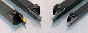
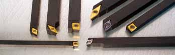
High performance tooling for automatic lathes
|
|
|
- かずただ おまた
- 5 years ago
- Views:
Transcription
1
2 High performance tooling for automatic lathes


3 1 2 7

4
 Special holders for shifted machining new Special holders for Tornos machines Spare parts WatchTools.")
5 pplication recommendations and standard machining data INFO & DT right hand cut left hand cut page for cam driven machines, (1) Tool with large insert (up to mm) Special holders for shifted machining new Special holders for Tornos machines Spare parts WatchTools. ow Vibration heavy metalholders W7 / W7 7Z / 7Z DCO 7 / 1 / 1 / 2 Micro 7sf+NOVIB SP PTS
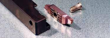
6 % rigid! The pplitec clamping system with shifted teeth patenterd Standard clamping system () Clamping system type B The insert can be changed in the machine, without removing the tool holder


7 7 ZX very efficient chip control for difficult materials new many different cutting geometries are possible min. = contact points 2 wiper effect for a better surface fi nish
8 Universal tough micrograin grades N (μk2) uncoated tough micrograin grade suitable for interrupted cut and other unfavourable machining conditions k2 + PVD thin coating grade for the machining of low resistance materials which causes edge buildup very low friction ratio not suitable for titanium machining k2 + PVD thin coating best universal grade first choice for steel, stainless steel and titanium alloys machining very good heat resistance Wear resistant micrograin grades HN (μk1) uncoated wear resistant micrograin grade suitable for the machining of low alloyed titanium not suitable for interrupted cut and other unfavourable machining conditions k1 + PVD thin coating grade for light machining of low resistance materials which causes edge buildup very low friction ratio not suitable for titanium machining k1 + PVD thin coating very wear resistant grade for light machining of steel, stainless steel and titanium alloys under favourable machining conditions
9 Cutting geometries : application recommendations series Cutting geometries steel Freecutting Steel steel Stainless luminium Titanium bronze Brass, Copper 1st choice recommended (see remarks here under) for fragile and very small workpieces _7 allround insert with efficient chip control _ standard flat geometry _ vs _ vx chipbreaker for light finishing operation very efficient chip control turnin _ x _9 standard positive geometry vibration reduction through flat ended cutting edge _7 N reinforced cutting edge (increases cutting force) allows easy regrinding 7 x vx standard positive geometry very efficient chip control g turnin vx1 vs very efficient chip control chipbreaker for light finishing operation >% zx Si very efficient chip control 7 parting off x xf x x2 u allows easy regrinding decreases cutting force, allows regrinding for difficult materials (reinforced point) very efficient chip control for long chipping sticky materials to narrow the chips, easy regrinding
10 Standard machining data Material Turning Cut off Vc Depth of cut Feed (m/min) (mm) (mm/rev) (m/min) (mm) (mm/rev) Vc Cutting width Feed Free cutting steel Steel Steel Steel Stainless Steel luminium Si <% luminium Si >% Titannium Copper brass bronze Indications for first setting roughing : average cutting speed high cutting feed finishing : high cutting speed low cutting feed Important remark : In many cases, it is impossible to reach the recommended cutting speed, due to the machine limits. pplitec tools are especially designed to be efficient even in bad cutting conditions. pplications not mentioned in the table above can also be efficient.
11 right hand cut front turning holders Solid carbide inserts, 11 () 27 N (μk2 ) H N (μk1 ) = =, =, =,1 =, BC C C 7 x 7 x 1 x 1 1 x 1 x x x 1 x 1 1 x 1 1 x 1 2 x = =,1 =,2 =, = =,1 = vs 2vs1 2vx =, 2vx HN (μk1) () 1, 1 1 2BC C = =,1 2x 2x1 C 7 x 7 x 1 x 1 1 x 1 x x x 1 x 1 1 x 1 1 x 1 2 x = =,1 =, HN (μk1),1
12 left hand cut front turning holders Solid carbide inserts (), N (μk2 ) H N (μk1 ) = =, =, =,1 =, C 7 x 7 x 1 x 1 x x x 1BC = =,1 =,2 =, = =, vs 1vs1 HN (μk1) (), C 1 x 1 1 x 1 1 x = =, 1vx 1vx 1 2 x BC C = =,1 1x 1x1 7 x 7 x 1 x BC BC 1BC 19 HN (μk1) x x x 1 x BC 19BC 11BC 11BC = =,1 =, ,1 C 1 x 1 1 x 1 2 x 2 1 1BC 11BC 1BC
13 right hand cut front turning holders Solid carbide inserts (), = 7 N (μk2 ) H N (μk1 ) =, =, =,1 =, C x 1 x 1 1 x = =,1 =,2 =, 1 2 HN (μk1) () x x x 1 x = =,1 vs vs1, C 1 x 1 1 x 1 2 x = vx =, vx 1 7N N (μk2 ) = =,1 x x1 r = ~,2 polished r = =, =,1 =,2 7N 7N 7N1 7N2 1 9 = =,1 =, HN (μk1),1
14 left hand cut front turning holders Solid carbide inserts (), N (μk2 ) H N (μk1 ) = 7 =, =, =,1 =, C x 1 x 1 x x x 1 x = =,1 =,2 =, = =,1 1 2 vs vs1 HN (μk1) (), C 1 x 1 1 x x 2 = vx =, vx 1 7N = =,1 x x1 r = ~,2 polished r = =, =,1 =,2 7N 7N 7N1 7N2 1 9 = =,1 =, HN (μk1),1
15 right hand cut 72 Special series for right hand turning cam driven machines holders C series 72 only with standard clamping system (type ) 1.2 see page : C 7 x 7 x 1 x 1 x blank insert ~7, cutting face polished 721P H N (μ K1 ) parting off H N (μ K1 ), 2, 1, 1,2 1,,,, 721, 7211, 7211, , 721,,, front turning,,, 722 H N (μ K1 ) 722 H N (μ K1 ) 722 H N (μ K1 )
16 left hand cut 71 Special series for left hand turning cam driven machines holders C series 71 only with standard clamping system (type ) 1.2 see page : C X 7 X 7 x 1 x 1 x blank insert ~7, cutting face polished 711P H N (μ K1 ) parting off 2,,,,9 1, 1,1 1, , 711, 711,9 7111, 7111,1 7111,2 H N (μ K1 ) 1, 1, 1,,,, 7111, 7111, , 711 H N (μ K1 ) front turning,,,,,, 7 H H N (μ K1 ) 7 H N (μ K1 ) 7 H N (μ K1 )
17 right hand cut back turning, 1, 1 2, 1, 1,2 1, 1, 1,2 2,1 2,, 2 1, 2,,,, 72, 721, 721, , 72 H N (μ K1 ), 2 1, 1, 1, 1,2 1, 1,,7,9 1,2 1,7 2 1, 2,,,, 72, 721, 721, , 72 H N (μ K1 ), 2 1, 1, 1, 1,2 1, 1,,,,7, 1, 2 1, 2,,,, 72, 721, 721, , 72 H N (μ K1 ) grooving and turning H N (μ K1 ) H N (μ K1 ),,,7,,9 1, 1,1 1, 1, 72, 72, 72,7 72, 72,9 721, 721,1 1,2 1, 1, 2, 2,,, 721,2 721, 721, 72 tronáonnage bstechen threading cut off W H N (μ K1 ) 1, 721, 72 W 1, 721, 72
18 left hand cut back turning 2, 1, 1,,9 1, 1,1 1,2 1, 1, 1, 1, 1, 1,2 1, 1,7 1,9 2,1 2,, 2 1, 1, 2, 2,,,,, 71, 71,9 711, 711,1 711,2 711, 711, , 71 H N (μ K1 ) 1 2 H N (μ K1 ) 2, 1, 1,,9 1, 1,1 1,2 1, 1, 1,,,,7,,9 1, 1,1 1,2 1,7 1, 1, 2, 2,,,,, 71, 71,9 711, 711,1 711,2 711, 711, , H N (μ K1 ) 2, 1, 1,,9 1, 1,1 1,2 1, 1, 1,,,,,,,,,7, 1, 1, 1, 2, 2,,,,, 71, 71,9 711, 711,1 711,2 711, 711, , 71 grooving and turning H N (μ K1 ) H N (μ K1 ),,,7,,9 1, 1,1 1, 1, 71, 71, 71,7 71, 71,9 711, 711,1 1,2 1, 1, 2, 2,,, 711,2 711, 711, 71 tronáonnage bstechen threading cut off W H N (μ K1 ) 1, 711, 71 W 1, 711, 71
19 right hand cut 71 cut off 72 turning front 7 turning back 7 cut in and turn 7 grooving 7 threading 77 with radius insert 71 right cut off line holders C rt. N standard clamping system () C clamping system type B 7 x 7 x 1 x 1 1 x 1 x x 1 x 1 1 x 1 1 x 1 2 x * * 77 : clamping only 2 pairs of screws for both clamping systems are included with each tool holder For small parts parting off C rt. N 7, x x 1 x 1 x C 7C1 7C 7C1 C use inserts type 71 see page : 1.1 C rt. N C 7, x x 1 x 1 x C 7C1 7C 7C1 use inserts type 71 see page : 1.2
20 left hand cut 71 cut off 72 turning front 7 turning back 7 cut in and turn 7 grooving 7 threading 77 with radius insert 71 left cut off line holders C rt. N standard clamping system () C clamping system type B 7 x 7 x 1 x 1 1 x 1 x x 1 x 1 1 x 1 1 x 1 2 x * * 77 : clamping only 2 pairs of screws for both clamping systems are included with each tool holder ight hand cut use inserts series 7 eft hand cut use inserts series 7 rt. N ~19 17 () , 19, , /7D1 7/7D19. 7/7D19.S 7/7D2 7/7D22 7/7D2 7/7D () 22 rt. N 7 / 7 D1
21 right hand cut blank insert cutting face polished 2, ~ 2, ~ 71 71P N (μk2 ) HN (μk1) N (μk2 ) HN (μk1) parting off N (μk2 ) HN (μk1),, 2, 1, 1,2 1, 2, , 711, 711, , 71 7,.. 1 1, x1, 71x 71x N (μk2 ) HN (μk1) /1,,, 1 1, , 7 71xf1, 2 71xf1, 71xf 71xf2, N (μk2 ) HN (μk1) 1, , 1, ,,,,,, 71x1, 71x 71x 71x21, 71x2 71x2 N (μk2 ) HN (μk1), u 71u N (μk2 ) HN (μk1), N (μk2 ) HN (μk1), 1, 7 71n1, 71n,
22 left hand cut blank insert cutting face polished ~ 2, ~ 2, 71 71P N (μk2 ) HN (μk1) N (μk2 ) HN (μk1) parting off N (μk2 ) HN (μk1) 2,,, 1, 1,2 1, 2, , 711, 711, , 71 7, 1.. 1, x1, 71x 71x N (μk2 ) HN (μk1) 1,, /1 2, xf 71xf 71xf2, N (μk2 ) HN (μk1),, N (μk2 ) HN (μk1) , 1, ,,,,,, 71x1, 71x 71x 71x21, 71x2 71x2 1, u 71u N ( K2 ) HN (μk1), N (μk2 ) HN (μk1), 1, 7 71n1, 71n,
23 right hand cut right cut off line main spindle subspindle Use 7 series holders, see page subspindle main spindle parting off N (μk2 ) H N (μk1 ) 2,, 1, 1,2 2, , 711, , N (μk2 ) H N (μk1 ) x.., N (μk2 ) H N (μk1 ) 1,, /1 2, xf 71xf 71xf2,, N (μk2 ) H N (μk1 ) ,, 71x 71x2 1 N (μk2 ) H N (μk1 ), 1, 7 71n1, 71n,
24 left hand cut left cut off line subspindle main spindle main spindle subspindle Use 7 series holders, see page 1.1. parting off N (μk2 ) H N (μk1 ),, 2 1, 1,2 2, , 711, , N (μk2 ) H N (μk1 ) x.., N (μk2 ) H N (μk1 ) /1,, 1 2, xf 71xf 71xf2,, 1 1 7, 2 7, 71x 71x2 H N (μ K1 ) 1 H N (μ K1 ), 1, 7 71n1, 71n,
25 right hand cut front turning, H N (μ K1 ) 1 H N (μ K1 ) 72x H N (μ K1 ) 72Px back turning,, 1 2,7 2,,, 1, 1,2, 7, 7, 7, 71, 71,2 7 H N (μ K1 ) 1 2,7,,, 1, 1,2, 7x, 7x, 7x, 7x1, 7x1,2 7x,2 2 2, ~1, 2,, 7vx 7vx N (μk2 ) H N (μ K1 ) 1,2 2 2,,,, 7vx1 7vx1 H N (μ K1 ) ,, 7vx H N (μ K1 )
26 left hand cut front turning, H N (μ K1 ) 1 H N (μ K1 ) 72x H N (μ K1 ) 72Px back turning 2 2,7 1,,,,, 1, 1,2, 7, 7, 7, 71, 71,2 7 H N (μ K1 ) 2,7 1,,, 1, 1,2, 7x, 7x, 7x, 7x1, 7x1,2 7x 2,, ~1 2 2,,2, 7vx 7vx H N (μ K1 ),, 2 2,,2 1, 7vx1 7vx1 H N (μ K1 ) ,, 7vx H N (μ K1 )
27 right hand cut tronáonnage bstechen back cut offturning / preparting off / 1 1 1, 1, 1, , 7P, 7P1, 7P1,2 7P H N (μ K1 ) grooving and turning,, 7,, 1, 7,,7 2 7,7, 2 7,,9 2, 7,9,9 7,9 1, 2, 71, 1, 2,, 71, 1,2 71,2 7, 7,2 72 1, 71, 7, 7,2 72 2, 72, H N (μ K1 ),, 1, 2 1,2 2, 1, 2, 7vs1, 7vs1,2 7vs 7vs1, 7vs 7vs2, H N (μ K1 ) 7XXXXB
28 left hand cut tronáonnage bstechen back cut offturning / preparting off 1 / 1 1, 1, 1, , 7P, 7P1, 7P1,2 7P H N (μ K1 ) grooving and turning,,,,7,,9 1, 1, 1,2 1, 2, 1, 2 2 2, 2,,,, 7, 7, 7,7 7, 7,9 71, 71, 71, , , H N (μ K1 ), 1, 2 1,2 2,, 1, 2, 7vs1, 7vs1,2 7vs 7vs1, 7vs 7vs2, H N (μ K1 ) 7XXXXB
29 right hand cut tronáonnage bstechen grooving cut off and turning 1 new , 2,, 2 1, 2, 1, 2,, 1,2,,2 1,,,2 2, 2, 1,1,1,,1,,1 7x, 7x1, 7x1, 7x1,2 7x 7x 7x2 7x1, 7x 7x 7x2 7x2, 7zx11, 7zx1 7zx1 7zx1 7zx1 7zx, H N (μ K1 ) H N (μ K1 ) new.. ±.1,2,,,2,, grooving H N (μ K1 ) 7XXXXB
30 left hand cut tronáonnage bstechen threading cut off H N (μ K1 ) new , 2,, 1, 1, 1,2 1, 2 2, 2,,,,,2 2, 2, 1,1,1,,1,,1 7x, 7x1, 7x1, 7x1,2 7x 7x 7x1, 7x 7x 7x2 7x2, 7zx11, 7zx1 7zx1 7zx1 7zx1 7zx, H N (μ K1 ) new.. ±.1,2,,,2,, grooving H N (μ K1 ) 7XXXXB
31 right hand cut tronáonnage bstechen threading cut off W H N (μ K1 ) W,2, ,xP ISO metric Pas Steigung Pitch P,2,,,,,,,7,7, 1, 1,2 1,7 1, 1, 1, 1, 1, 1, 1, 1, 1, full profile,,, 7M,2 7M, 7M, 7M, 7M, 7M, 7M, 7M,7 7M,7 7M, 7M1, 7M1,2 7M 7M1,7 H N (μ K1 ), 2 partial profile P,, 7 H N (μ K1 ) Other profil types on request See also series 7 / 7 on pages tronáonnage bstechen insert cut off with radius H N (μ K1 ),2,,,7, 1, 2, 2, 77,2 77, 77, 77,7 77, 771, 7XXXXB
32 ( left hand cut tronáonnage bstechen threading cut off W H N (μ K1 ) W,2, ISO metric,xp Pas Steigung Pitch P,2,,,,,,,7,7, 1, 1,2 1,7 full profile 1, 1, 1, 1, 1, 1, 1, 1, 1,,,, 7M,2 7M, 7M, 7M, 7M, 7M, 7M, 7M,7 7M,7 7M, 7M1, 7M1,2 7M 7M1,7 H N (μ K1 ) 2, partial profile P,, 7 H N (μ K1 ) Ot her profil types on request See also series 7 / 7 on pages tronáonnage bstechen insert cut off with radius,,,7, 1, 2, 2, 77, 77, 77,7 77, 771, N ( K2 ) H N K1 ) 7XXXXB
33 right hand cut 71 cut off front turning back turning cut in and turn threading insert with radius right cut off line holders C standard clamping system () C 1 x 1 1 x 1 x x clamping system type and B 2 pairs of screws for both clamping systems are included with each tool holder C 1 x 1 x x 1 x 1 1 x 1 1 x 1 1 x 1 2 x B 7B 79B standard clamping system () 2 / C 2 x / 72
34 left hand cut 71 cut off front turning back turning cut in and turn threading insert with radius left cut off line holders C standard clamping system () C 1 x 1 1 x 1 x x clamping system type and B 2 pairs of screws for both clamping systems are included with each tool holder C 1 x 1 x x 1 x 1 1 x 1 1 x 1 1 x 1 2 x B 7B 79B C 2 / 2 x / 72
35 right hand cut For small parts parting off C holders C x 1 x 1 7C 7C1 1 7, SPCI TONOS S1 / SS1 1, 19, 2,2 7S 9 11, 7, with inserts type 71 see page : 1. 2,2 7SH11, 9 7, 7, 7,, parting off POSITIV CUT , 2, 1, 2, 7, 9 9 7, S1, 71S 71S2, 71S1,1 71S1 71S2,1 H N (μ K1 ) with inserts type 71S / D,, 1, 1 1, 1,2 1 1, 1, , 1 71D1, 71D1,1 71D1,2 71D 71D1 71D1, 71D1, 71D 71D1 71D2, H N (μ K1 )
36 right hand cut left hand cut holders C 1 x 1 7C1 C 1 use inserts type 71 see pages : ight hand cut use inserts series 7 eft hand cut use inserts series , 19, /7D1 7/7D19, 7/7D19,S 22 () ÿ , 2, /7D2 7/7D22 7/7D2 7/7D2, 7/7D2,S / 7 D1 () 2 blank insert H N (μ K1 ) H N (μ K1 ) ~1, 71 ~1, 71 cutting face polished cutting face polished ~1, H N (μ K1 ) ~1, H N (μ K1 ) 71P 71P 7XXXXB
37 right hand cut parting off,, 1 1, 1,2 1, 2,2 2,, 7, 7, , 711, , 71 7,2 7, 71, H N (μ K1 ) 1 2,2 2,, s 71s2,2 71s2, 71s,, H N (μ K1 ), , 7, ,,. 1 2, 7, x 71x 71x2, H N (μ K1 ). /1,,, 1 2,2 2,, 7, xf 71xf 71xf2,2 71xf2, 71xf, H N (μ K1 ) 1 1, , 2, 7, 1 1 7, 1 1,,,,,, 71x 71x 71x2, 71x2 71x2 71x22, H N (μ K1 ),1 x,, u H N (μ K1 ),1 x,, 2,, nxf 71nxf2, 71nxf, H N (μ K1 )
38 left hand cut parting off 1,, 1, 1,2 1, 2,2 2,, 7, 7, , 711, , 71 7,2 7, 71, H N (μ K1 ) 1 2,2 2,, s 71s2,2 71s2, 71s, 1 1,,2 2, 7, , H N (μ K1 ), x H N (μ K1 ).. 1,,, /1 7, 1 2,2 1 2, 1, 1 71xf 71xf 71xf2,2 71xf2, 71xf, H N (μ K1 ) 1, , 2, 7, 1 1 7, 1 1,,,,,, 71x 71x 71x2, 71x2 71x2 71x22, H N (μ K1 ),1 x u,, H N (μ K1 ) 2,, nxf 71nxf2, 71nxf,,1 x, H N (μ K1 ),
39 right hand cut right cut off line subspindle main spindle Use 7 series holders, see pages 1.1 and 1.2. subspindle main spindle parting off H N (μ K1 ) 1,, 1, 1, 2,2 2,, 7, 7, , , 71 7,2 7, 71, 1 1, 2,2 2,,, s1, 71s 71s 71s2,2 71s2, 71s, 1,2,, 7, H N (μ K1 ) , 1 2, 1 71x 71x 71x2, H N (μ K1 ) 7XXXXB
40 left hand cut right cut off line subspindle main spindle subspindle Use 7 series holders, see pages 1. and 1.. main spindle parting off,, 1 1, 1, 2,2 2,, 7, 7, , , 71 7,2 7, 71, H N (μ K1 ) 1 1, 2,2 2,, s1, 71s 71s 71s2,2 71s2, 71s,,2,, 1 7, H N (μ K1 ) x H N (μ K1 ).. 7XXXXB
41 right hand cut right cut off line subspindle main spindle Use 7 series holders, see pages 1.1 and 1.2. subspindle main spindle parting off, /1 1,, 7, 1 2, 1, 1 71xf 71xf 71xf2, 71xf, H N (μ K1 ), ,, 1, 2 1, 71x 71x 71x2 H N (μ K 1 ),,1 x,1 x 2,, nxf 71nxf2, 71nxf, H N (μ K1 ), 7XXXXB
42 left hand cut right cut off line subspindle main spindle subspindle Use 7 series holders, see pages 1. and 1.. main spindle parting off, /1,, 1 2,, xf 71xf2, 71xf, H N (μ K1 ), , 71x H N (μ K1 ) 2 1, 71x2,1 x,1 x, 2,, nxf 71nxf2, 71nxf, H N (μ K1 ), 7XXXXB
43 right hand cut front turning, H N (μ K1 ) 2 72, H N (μ K1 ),2 72x 72x2 H N (μ K1 ) 72Px n f multifunction turning front turning back turning 1,, 1 72s H N (μ K1 ) 7s H N (μ K1 ) back turning / preparting off / , 2,2 2,,,, 7P 7P1, 7P 7P2,2 7P2, 7P, H N (μ K1 ) 7XXXXB
44 left hand cut front turning, H N (μ K1 ) ,2 72x 72x2 H N (μ K1 ) 72Px H N (μ K1 ) f multifunction turning front turning back turning, 1, 1 72s H N (μ K1 ) 7s H N (μ K1 ) back turning / preparting off 1 / 1 1 1, 2,2 2,,,, 7P 7P1, 7P 7P2,2 7P2, 7P, H N (μ K1 ) 7XXXXB
45 right hand cut tronáonnage bstechen back cut offturning H N (μ K1 ), 1, 1, 2, 7, 9, 71, 71, , 2 1 1, 1, 1, 2, 2, 7, 7, 9 9,,2,2,2,2 7x1, 7x1, 7x1,2 7x 7x2 7x 7x2 7x2, 7x2,2 H N (μ K1 ) back turning for deep cut 1 9 1, 2,2 7xs1, 7xs1,2 H N (μ K1 ),2 ~1 9, 7vx 7vx H N (μ K1 ), 1,2, 9, 7vx1 7vx1 H N (μ K1 ) 7XXXXB
46 left hand cut tronáonnage bstechen cut back offturning, 1, 1, 2, 7, 9, 71, 71, , H N (μ K1 ) 2 1 1, 1, 1, 2, 2, 7, 7, 9 9,,2,2,2,2 7x1, 7x1, 7x1,2 7x 7x2 7x 7x2 7x2, 7x2,2 H N (μ K1 ) back turning for deep cut 2 9 1, 1,2 7xs1, 7xs1,2 H N (μ K1 ) 9 ~1,2, 7vx 7vx H N (μ K1 ), 9,,2 1, 7vx1 7vx1 H N (μ K1 ) 7XXXXB
47 tronáonnage bstechen back cut offturning 2, 9 1, new, 7vx new,1 7zx11. right hand cut H N (μ K1 ) 7XXXXB
48 2 tronáonnage bstechen cut back offturning , 9 new 1,, 7vx new,1 7zx11. left hand cut H N (μ K1 ) 7XXXXB
49 right hand cut tronáonnage bstechen cut grooving off and turning H N (μ K1 ) 1 1,,7, 2 2,9 1, 1, 1,2 1, 2, 2,,,,2,,2 2, 2,,2,,,,,2, 7, 7,7 7, 7,9 71, 71, 71, , , 72,2 7, 7, 7,2 7, 1 1, 1, 1,2 2,, 2 2, 7vs1, 7vs1,2 7vs 7vs 7vs2, 7vs, H N (μ K1 ) H N (μ K1 ) 1 1 new , 2,,,, 1, 1, 1,2 1, 2, 2,,,,,, 2, 2, 1,,,2,,2,2,,2,2,,,,2,,2,,2,2 7x1, 7x1, 7x1,2 7x 7x 7x2 7x1, 7x 7x 7x2 7x2, 7x2,2 7x, 7x, 7x,2 7x, 7x,2 7zx11. 7zx11. 7zx. 7zx.2 7zx. 7zx.2 7zx1. 7zx1.2 7zx1.2 for Feed from.2 mm
50 left hand cut tronáonnage bstechen cut grooving off and turning, 7,,7 2 7,7,9 7,9 1, 2, 71, 1, 2,, 71, 1,2 71,2 7, 7 1, 71, 1 7, 7 1,2 72 2, 72,, 7,,, 7,,,2 7,2, 7, H N (μ K1 ), 1 1 1, 1,2 2,, 2 2, 7vs1, 7vs1,2 7vs 7vs 7vs2, 7vs, H N (μ K1 ) for Feed from.2 mm 1 1 new 1 2,, 1, 1, 1,2 1, 2, 2,,,,,, 2, 2, 1,,,2,,2,2,,2,2,,,,, 7x1, 7x1, 7x1,2 7x 7x 7x2 7x1, 7x 7x 7x2 7x2, 7x2,2 7x, 7x, 7x,2 7x, 7x,2 7zx11. 7zx11. 7zx. 7zx. 7zx1. H N (μ K1 )
51 right hand cut tronáonnage bstechen threading cut off W H N (μ K1 ) W,,,2, , 72 7,xP 2 ISO metric Pas Gewinde Pitch P, 1, 1,2 1,7 full profile 2, 7M, 2, 7M1, 2, 7M1,2, 9 7M, 9 7M1,7, 9 7M H N (μ K1 ) 2 partial profile 1, 9 P,, 1,7,,,2 7G 7G H N (μ K1 ), Other profil types on request See also series 7 / 7 on pages ,1,2 new , 1, 2, 1, 1,, insert with radius 77, 771, zx11, 77zx1 77zx1 H N (μ K1 ) 7XXXXB
52 left hand cut tronáonnage bstechen threading cut off W H N (μ K1 ) W,,,2, , 72 7 ISO metric 2,xP Pas Gewinde Pitch P, 1, 1,2 1,7 full profile 2, 7M, 2, 7M1, 2, 7M1,2, 9 7M, 9 7M1,7, 9 7M H N (μ K1 ) 2 partial profile 9 1, P,, 1,7,,,2 7G 7G H N (μ K1 ), Other profil types on request See also series 7 / 7 on pages insert with radius 1,2 new.2.1,1 1, 1, 2, 1, 1, 77, 771, zx11, 77zx1 77zx1 H N (μ K1 ) 7XXXXB
53 right hand cut holders blank insert C C x x 1 x 1 1 x 1 1 x 1 1 x 1 2 x 2 2 x 2 standard clamping system (type ) ~17 71 N ( K2 ) parting off, 1 2,,, , 71, 71,, /1,,, 1 2,,, xf 71xf2, 71xf, 71xf, right cut off line main spindle subspindle Use 77 series holders. (see page 1.1) subspindle main spindle 1,, 1, 1,2 2,,,, , 7711, , 771, 771, 1,,, /1 2,,, xf 771xf2, 771xf, 771xf,
54 left hand cut holders blank insert C standard clamping system (type ) C x x 1 x 1 1 x 1 1 x 1 1 x 1 2 x 2 2 x N ( K2 ) ~17 parting off 1, 2,,, , 771, 771,, 1,, /1 2,,, xf2, 771xf, 771xf,, right cut off line main spindle subspindle Use 7 series holders. (see page 1.) subspindle main spindle, 1 2,,, , 71, 71,, /1,, 1 2,,, xf2, 71xf, 71xf,,
55 right hand cut blank insert C C 1 x 1 1 x 1 2 x 2 2 x ~2 standard clamping system (type ) 71 parting off, 1 2,,, , 71, 71,,,2,, 1, 22 71xf, N ( K2 ) right cut off line main spindle subspindle Use 7 series holders. (see page 1.) subspindle main spindle 1, 2,,, , 71, 71,, 1,,2, 22 71xf,,
56 left hand cut blank insert C C 1 x 1 1 x 1 2 x 2 2 x ~2 standard clamping system (type ) 71 parting off, 22 71, 1,, 1,,2, 22 71xf,, right cut off line main spindle subspindle Use 7 series holders. (see page 1.2) subspindle main spindle, 22 71,, 1,,2,, 1, 22 71xf,,
57 μ turning tool series 7 with large insert right left tool holder C C C C x 1 x 1 2 x 2 1 W7 1 W71 W72 x 1 x 1 2 x 2 1 W7 1 W71 W72 blank insert W71 W71 11 W71 11 W71,1,1
58 right hand cut Special holders for shifted machining C Z H tool ref. line C Z H Z x 1 x , 1, 1, 1, 7z 7z1 use inserts series 7 see pages : C Z H C Z H x 1 x z 7z1 use inserts series 7 see pages :
59 Special holders for TONOS DCO 7 / 1 mm machine right cut right hand cut 7 DCO 1 To be used on TONOS short tool holder right TONOS N use inserts series 7 see pages standard clamping system () only right cut off line 7 DCO 1 71 see page 7, To be used on TONOS short tool holder right TONOS N
60 Special holders for TONOS DCO 7 / 1 mm machine left cut left hand cut To be used on TONOS short tool holder left 7 DCO 1 TONOS N 7 use inserts series 7 see pages standard clamping system () only left cut off line 7 DCO 1 71 see page To be used on TONOS short tool holder left TONOS N 7 7,
61 Special holders for TONOS DCO 7 / 1 mm machine For small parts parting off holders right hand cut with adjustment screw 7 DCO 1 parting off tool ref. line tool ref. line (1), (1),,, H N (μ K1 ) 1, 1, 1,2 1 1, 1, , 1 71D1, 71D1,1 71D1,2 71D 71D1 71D1, 71D1, 71D 71D1 71D2, , 2,2 2,,, s1, 71s 71s 71s2,2 71s2, 71s, H N (μ K1 )
62 Special holders for TONOS DCO 7 / 1 mm machine For small parts parting off holders left hand cut with adjustment screw 7 DCO 1 parting off,,,, line ref. tool H N (μ K1 ) 1, 71D1, (1) 1, 71D1,1 1,2 71D1,2 (1) 71D 71D1 1, 71D1, 1, 1 71D1, 1 71D 1 71D1 line ref. tool , 2,2 2,,, s1, 71s 71s 71s2,2 71s2, 71s, H N (μ K1 )
63 right hand cut Special holders for TONOS DCO 1 and DCO 2 machines For small parts parting off holders DCO 1 Integrated cooling (xternal connection G1/) 77 DCO 1 DCO 2 Integrated cooling 77 DCO 2 parting off 1, line ref. tool 1,2 7, 1 (1) 1 771D1,2 771D 771D,, line ref. tool 1, 1,2 2,,, 2,,,, , 7711, , 771, 771, 1, 771xf 771xf2, 771xf, 771xf, N (μk2),, N (μk2), /1


64 Tools for TONOS Micro D1 2. D1F11. S7. S. S7. 77 fi xturing rod fi xturing rod with 11 collet holder holder, inserts serie 7 (see pages ) holder for X square tool holder, inserts serie 7 (see pages ) parting off tool serie 77 (see page 1.1)


65 Special turning tools for watch industry SF new Geometry developed for watch parts machining Wear resistant micrograin grade Tool for machining of very small parts Series 7sf adapted for CNC machines Series 71sf adapted for cam driven machines xample part 1, ±,1, +,1 Ø,2 +, Ø,1 +,,2 +,1, ±,1 Ø
66 new Special turning tools for watch industry right hand cut 1 2. front turning roughing 72sf/ H N (μ K1 ). front turning finishing sf1/ H N (μ K1 ) 2 2. back turning..1 7sf1/ H N (μ K1 ).2 2 parting off, 1, 71sf. 71sf1. use holder series 7 page 1.1 7XXXXB
67 Special turning tools for watch industry new 1 front turning roughing H N (μ K1 ) 2. 7sf/. front turning finishing sf1/ H N (μ K1 ) back turning sf1/ H N (μ K1 ).2 parting off 2, 1, 711sf. 711sf1. use holder series 71 page 1.1

68 new ow vibration heavy metal holders 71NOVIB C C x 7 x 7 x NOVIB 717NOVIB 71NOVIB 7NOVIB 7NOVIB C C C C 7 x 7 x NOVIB 7NOVIB 7 x 7 x NOVIB 7NOVIB
69 TOPline clamping systems Spare screws and keys % rigid! holder standard clamping system clamping system type B Type 11 >>> 1 22 >>> 2 2 >>> 2 >>> VM2,x,T VM2,x7,T VM2,x7,T VM2,x7,T VM2,x7,T Type >>> >>> >>> 71 7DCO1 7DCO1 7C VM2,x,T VM2,x,T VM2,x7,T VM2,x,T VM2,x.T VM2,x7,T VMx7T VMx7T VMx7T VMx7T VMx,T VM2,x7,T CT 7 77 >>> 71 7/7D 7C 7DCO1 7DCO1 7Z VMx7T VMx7T VMx,T VMx7T VMx7T VMx9T VM2,x7,T CT B 7 7B S 7C 7DCO1 VMx9T1 VMx9T1 VMx9T1 VMx9T1 VMx9T1 VMx9T1 VMx9T1 VMx9T1 VMx7,T1 VMx7,T1 VMx,T1 VMx1BN21 CP VMxBN11 CP2, VMx1BN11 CP2, VMx1BN11 CP2, VMxBN11 CP2, VMx1BN11 CP2, standard clamping system () B 7 7B /72 7/7D 7C 7DCO1 7Z VMx9T1 VMx9T1 VMx9T1 VMx9T1 VMx9T1 VMx9T1 VMx9T1 VMx9T1 VMx9T1 VMx9T1 VMx7,T1 VMx,T1 VMxT1 VMx1BN21 CP VMxBN11 VMx1BN11 VMx1BN11 VMxBN11 VMx1BN11 CP2, CP2, CP2, CP2, CP2, clamping system type B >>> DCO1 77DCO2 7 >>> >>> >>> 72 W7 W W7 VMx9T1 VMx7,T1 VMx7,T1 VMx9T1 VMx9T1 VMx9T1 VMx11T1 VMx11T1
70
71 Index Type page Data and grades INFO & DT Ø max mm H 2. Ø max 2 mm HX 2. UN 2. U U 2. new TN 2.7 GN 2.
72 TiN PVD coating new PVD thin coating PVD coating Tmax PVD coating universal grade good impact resistance best universal grade very good wear resistance grade for medium to heavy machining of steel, stainless steel and alloyed steel for machining of steel, stainless steel and titanium alloys in unfavourable machining conditions new HTX PVD coating first choice for steel, stainless steel and titanium alloys machining S PVD coating high machining heat resistance first choice for the machining of carbon steel and high alloyed steel complementary grade highly wear resistant for machining for steel with high abrasion for machining with low cutting feed for carbon steel, high alloyed steel and stainless steel grade for nonferrous materials very low friction ratio first choice for luminium up to 1 % Si, Copper and low alloyed Titanium not suitable for interrupted cut
73 Standard machining data Cut off Material Vc (m/min) U F (mm/u) cutting geometries T F (mm/u) Freecutting steel Steel < N/mm Steel < N/mm Steel > N/mm Stainless steel luminium Titanium.2. Copper, brass, bronze Turning Material Vc (m/min) CUT22 F (mm/u) G F (mm/u) CUT1 F (mm/u) Freecutting steel Steel Steel Steel < N/mm < N/mm > N/mm Stainless steel luminium Titanium Copper, brass, bronze
74 Ø max mm Holders Ø max. C 1 (2) B Insert x B x Ø max. 1 C rt. N rt. N W 1. mm CUT1 W 2.2 mm CUT22 W.1 mm CUT1 x 1 x 11 (2=2) 1 1 x 1 x 11 1 x x 1 1 x x x 1 x x 1 x1 1 2 x 2 x 1 1 x x 11 2 x x 1 2 x x x 1 x x 1 x x 2 x 2 1 x 1 x 1 2 x 2 x 2 x 2 x CUT1H1 CUT1H CUT1H11 CUT1H CUT1H CUT1H CUT1H9 CUT1H CUT1H11 CUT1H CUT1H11 CUT1H CUT1H22 CUT1H22. 2 CUT22H1 CUT22H1. 2 CUT22H CUT22H. 2 CUT22H9 CUT22H9. 2 CUT22H11 CUT22H11. 2 CUT22H11 CUT22H11. 2 CUT22H22 CUT22H22 7. CUT1H11 CUT1H11 7. CUT1H22 CUT1H22 7. CUT1H22 CUT1H22 Spare parts rt. N CUT1ST CUT22ST CUT1ST rt. N CUT1ST CUT22ST CUT1ST
75 Ø max 2 mm Holders Ø max. C 1 2 B Insert x B x Ø max. 1 C 2 rt. N rt. N W 1. mm CUT1 W 2.2 mm CUT22 W.1 mm CUT1 1 x x CUT1H1X CUT1H1X x x CUT1HX CUT1HX x x CUT1HX9 CUT1HX9 1 x 1 x CUT1H11X CUT1H11X 1 x 1 x CUT1H11X CUT1H11X 2 x 2 x CUT1H22X CUT1H22X 1 x x CUT22H1X CUT22H1X x x CUT22HX CUT22HX x x CUT22HX9 CUT22HX9 1 x 1 x CUT22H11X CUT22H11X 1 x 1 x CUT22H11X CUT22H11X 2 x 2 x 2. 2 CUT22H22X CUT22H22X 1 x 1 x CUT1H11X CUT1H11X 2 x 2 x CUT1H22X CUT1H22X 2 x 2 x CUT1H22X CUT1H22X rt. N rt. N Spare parts CUT1XST CUT1XST CUT22XST CUT22XST CUT1XST CUT1XST
76 Solid carbide cut off inserts W Type W +/. rt. N HTX TiN Tmax S CUT1 CUT22 CUT CUT1UN.1 CUT1UN1.2 CUT22UN.2 CUT22UN2.2 CUT1UN.2 CUT1UN2 W W Type W +/. rt. N rt. N TiN Tmax CUT CUT1U CUT1U1 CUT1U CUT1U CUT22U CUT22U CUT CUT22U2 CUT22U CUT22U1 CUT22U1 CUT CUT1U CUT1U CUT1U2 CUT1U2 CUT1U1 CUT1U1 use holder type H or HX, see p

77 new Solid carbide cut off inserts 2mm W TN Type W +/. rt. N TiN Tmax CUT CUT22TN2 CUT1.1.2 CUT1TN2 use holder type H or HX, see p Characteristic of TN inserts Ø 2mm 7 Medium high feed

78 Solid carbide inserts for grooving and turning W T Type W +/. T rt. N TiN Tmax S CUT CUT22GN2 CUT1.1.1 CUT1GN2 use holder type H, see p. 2. pplication recommendations for GN inserts ap (mm) CUT22GN CUT1GN ap T 2 ap max=t in material with good machinability 1,,1,1 F (mm/u) / Vc (m/min) F (mm/u) Material / Vc (m/min) F (mm/u) see p. 2.
79
80 Index page Data and grades INFO & DT.2. FNX. NPX. FNX17. NPX17. Inserts cutting geometries FNX2. NPX2. F/X1 FNK1 FN.7. NXF. NMF.9 NHF.9 Holders and inserts.1.1 Holders and inserts.1.19 Holders and inserts.2.2
81 Insert grades TiN PVD coating PVD coating PVD coating universal grade for light machining very low friction ratio which causes edge buildup not suitable for titanium machining universal grade good heat resistance titanium alloys machining very wear resistant grade very good heat resistance not suitable for interrupted cut and other unfavourable machining conditions Tmax Ti K1 K2 PVD coating CVD coating uncoated uncoated grade for medium to heavy machining of steel, alloys steel and stainless steel very low friction ratio high machining heat resistance strong and very versatile grade for medium to heavy machining of steel and stainless steel high machining heat resistance wear resistant micrograin grade suitable for titanium machining not suitable for interrupted cut tough micrograin grade coating suitable for interrupted cut
82 Standard machining data Vc m / min Grades Material PVD CVD uncoated Tmax Ti K1 K2 Freecutting steel Steel Steel Steel 1 1 Stainless steel luminium luminium Titanium 7 Copper, brass, bronze pplication recomendations a machining depth / tool radius ratio H a for a better suface finish and better machining stability, choose a tool geometry with angle aª as small as possible H min =,7 x max = 1, x H

83 cutting geometries Type FNX sharp cutting edge polished materials : see page. Description polished and ground insert sharp cutting edge positive cut with controlled chipbreaking micrograin grades with PVD coatings pplication finishing general purpose geometry for the machining of all materials feed rate F =,1,1 mm Type NPX polished cutting edge polished materials : see page. Description polished and ground insert reinforced and polished cutting edge positive cut with controlled chipbreaking micrograin grades with PVD coatings pplication finishing and semifinishing steel and stainless steel machining feed rate F =,,1 mm


84 cutting geometries Type FNX17 polished materials : sharp cutting edge see page. Description polished and ground insert sharp cutting edge 17 positive cut with controlled chipbreaking micrograin grades with PVD coatings pplication finishing machining of aluminium alloys, nonferrous materials and stainless steel feed rate F =,1,2 mm Type NPX17 polished materials : polished cutting edge see page. Description polished and ground insert reinforced and polished cutting edge 17 positive cut with controlled chipbreaking micrograin grades with PVD coatings pplication finishing and semifinishing steel and stainless steel machining feed rate F =,,1 mm


85 cutting geometries Type FNX2 polished materials : sharp cutting edge see page. Description polished and ground insert sharp cutting edge 2 positive cut with controlled chipbreaking micrograin grades with PVD coatings pplication finishing machining of aluminium alloys, nonferrous materials and stainless steel feed rate F =,1,2 mm Type NPX2 polished materials : polished cutting edge see page. Description polished and ground insert reinforced and polished cutting edge 2 positive cut with controlled chipbreaking micrograin grades with PVD coatings pplication finishing and semifinishing steel and stainless steel machining feed rate F =,,1 mm
86 cutting geometries Type F/X1 available only in execution type VCGT11... sharp cutting edge polished Material new corner radius starting. mm see page :. Description polished and ground insert sharp cutting edge 1 positive cut with controlled chipbreaking micrograin grades with PVD coatings pplication finishing general purpose geometry for the machining of all materials feed rate F =.1.1 mm / U Type FNK1 sharp cutting edge available only in execution type VCGT11 Description polished and ground insert sharp cutting edge 1 positive cut with controlled chipbreaking micrograin grades with PVD coatings pplication finishing general purpose geometry for the machining of all materials feed rate F =,1,1 mm

87 cutting geometries Type FN sharp cutting edge available only in execution type VCGT11 Description polished and ground insert sharp cutting edge neutral cut micrograin grades with PVD coatings pplication finishing brass machining feed rate F =,1,1 mm Type NXF materials : see page. smallest cutting edge treatment Description unground insert positive cut with controlled chipbreaking special treatment for smallest cutting edge rounding PVD and CVD coatings pplication semifinishing and finishing steel and stainless steel machining feed rate F =,,1 mm


88 cutting geometries Type NMF materials : see page. cutting edge treatment Description unground insert positive cut with controlled chipbreaking special treatment for cutting edge rounding PVD and CVD coatings pplication medium turning steel and stainless steel machining feed rate F =,, mm Type NHF materials : see page. cutting edge treatment Description unground insert positive cut with controlled chipbreaking special treatment for cutting edge rounding CVD coating pplication medium turning and roughing steel and stainless steel machining feed rate F =,1, mm
89 turning tools holders 1 ISOCode rt. N X insert SCCX ISO22 x x 11 CC..2.. SCC11X ISO2 1 x 1 x 11 CC..2.. SCCX ISO2 x x 1 CC..2.. SCCG ISO29 x x 9 CC..2.. SCC11X ISO2 1 x 1 x 1 CC..2.. SCC11F ISO27 1 x 1 x 7 CC..2.. SCCX9 ISO222 x x 1 CC..9T.. SCCG9 ISO2229 x x 9 CC..9T.. SCC11X9 ISO222 1 x 1 x 1 CC..9T.. SCC11F9 ISO x 1 x 7 CC..9T.. SCC22X9 ISO222 2 x 2 x CC..9T.. ISOCode rt. N X insert SCCX ISO2 x x 11 CC..2.. SCC11X ISO21 1 x 1 x 11 CC..2.. SCCX ISO21 x x 1 CC..2.. SCCG ISO219 x x 9 CC..2.. SCC11X ISO21 1 x 1 x 1 CC..2.. SCC11F ISO217 1 x 1 x 7 CC..2.. SCCX9 ISO22 x x 1 CC..9T.. SCCG9 ISO229 x x 9 CC..9T.. SCC11X9 ISO22 1 x 1 x 1 CC..9T.. SCC11F9 ISO227 1 x 1 x 7 CC..9T.. SCC22X9 ISO22 2 x 2 x CC..9T..
90 holders N ISOCode rt. N X insert SCMCNX ISO2 x x 11 CC..2.. SCMCN11X ISO21 1 x 1 x 11 CC..2.. SCMCNX ISO21 x x 1 CC..2.. SCMCNG ISO219 x x 9 CC..2.. SCMCN11X ISO21 1 x 1 x 1 CC..2.. SCMCN11F ISO217 1 x 1 x 7 CC..2.. SCMCNX9 ISO22 x x 1 CC..9T.. SCMCNG9 ISO229 x x 9 CC..9T.. SCMCN11X9 ISO22 1 x 1 x 1 CC..9T.. SCMCN11F9 ISO227 1 x 1 x 7 CC..9T.. SCMCN22X9 ISO22 2 x 2 x CC..9T.. 1 ISOCode rt. N X insert SCCX ISO21 x x 11 CC..2.. SCC11X ISO211 1 x 1 x 11 CC..2.. SCCX ISO211 x x 1 CC..2.. SCCG ISO2119 x x 9 CC..2.. SCC11X ISO211 1 x 1 x 1 CC..2.. SCC11F ISO x 1 x 7 CC..2.. SCCX9 ISO221 x x 1 CC..9T.. SCCG9 ISO2219 x x 9 CC..9T.. SCC11X9 ISO221 1 x 1 x 1 CC..9T.. SCC11F9 ISO x 1 x 7 CC..9T.. SCC22X9 ISO221 2 x 2 x CC..9T.. ISOCode rt. N X insert SCCX ISO2 x x 11 CC..2.. SCC11X ISO21 1 x 1 x 11 CC..2.. SCCX ISO21 x x 1 CC..2.. SCCG ISO219 x x 9 CC..2.. SCC11X ISO21 1 x 1 x 1 CC..2.. SCC11F ISO217 1 x 1 x 7 CC..2.. SCCX9 ISO22 x x 1 CC..9T.. SCCG9 ISO229 x x 9 CC..9T.. SCC11X9 ISO22 1 x 1 x 1 CC..9T.. SCC11F9 ISO227 1 x 1 x 7 CC..9T.. SCC22X9 ISO22 2 x 2 x CC..9T.. Spare screws and keys series ISO2 series ISO22 VM2.x7.T VMx9T1ISO CT CT1
91 Solid carbide inserts PVD coated CVD uncoated CCGT FNX ~ ~9 ISOCode rt. N. CCGT2FNX ISO11.1 CCGT21FNX ISO111.2 CCGT22FNX ISO1. CCGT2FNX ISO11. CCGT9TFNX ISO.1 CCGT9T1FNX ISO1.2 CCGT9T2FNX ISO2. CCGT9TFNX ISO TiN Tmax Ti K1 K2 CCGT ~. CCGT2NPX ISO11P.1 CCGT21NPX ISO111P.2 CCGT22NPX ISO1P. CCGT2NPX ISO11P NPX ~9. CCGT9TNPX ISOP.1 CCGT9T1NPX ISO1P.2 CCGT9T2NPX ISO2P. CCGT9TNPX ISOP CCGT ~. CCGT2FNX17 ISO11.1 CCGT21FNX17 ISO111.2 CCGT22FNX17 ISO1. CCGT2FNX17 ISO11 FNX17 ~9. CCGT9TFNX17 ISO.1 CCGT9T1FNX17 ISO1.2 CCGT9T2FNX17 ISO2. CCGT9TFNX17 ISO. CCGT9TFNX17 ISO CCGT NPX17 ~ ~9. CCGT2NPX17 ISO11P.1 CCGT21NPX17 ISO111P.2 CCGT22NPX17 ISO1P. CCGT2NPX17 ISO11P. CCGT9TNPX17 ISOP.1 CCGT9T1NPX17 ISO1P.2 CCGT9T2NPX17 ISO2P. CCGT9TNPX17 ISOP. CCGT9TNPX17 ISOP
92 Solid carbide inserts CCGT FNX2 CCGT NPX2 CCMT ~ ~9 ~ ~9 ~ ISOCode rt. N TiN PVD Tmax CVD Ti K1 K2. CCGT2FNX2 ISO11.1 CCGT21FNX2 ISO111.2 CCGT22FNX2 ISO1. CCGT2FNX2 ISO11. CCGT9TFNX2 ISO.1 CCGT9T1FNX2 ISO1.2 CCGT9T2FNX2 ISO2. CCGT9TFNX2 ISO. CCGT9TFNX2 ISO. CCGT2NPX2 ISO11P.1 CCGT21NPX2 ISO111P.2 CCGT22NPX2 ISO1P. CCGT2NPX2 ISO11P. CCGT9TNPX2 ISOP.1 CCGT9T1NPX2 ISO1P.2 CCGT9T2NPX2 ISO2P. CCGT9TNPX2 ISOP. CCGT9TNPX2 ISOP.2 CCMT22NXF ISO11. CCMT2NXF ISO111 coated uncoated NXF ~9.2 CCMT9T2NXF ISO. CCMT9TNXF ISO1. CCMT9TNXF ISO1 CCMT ~.2 CCMT22NMF ISO12. CCMT2NMF ISO1 NMF ~9.2 CCMT9T2NMF ISO22. CCMT9TNMF ISO2. CCMT9TNMF ISO2 CCMT ~. CCMT2NHF ISO119. CCMT2NHF ISO119 NHF ~9. CCMT9TNHF ISO9. CCMT9TNHF ISO9
93 turning tools holders ISOCode rt. N X insert SDCX7 ISO222 x x 11 DC SDC11X7 ISO22 1 x 1 x 11 DC SDCX7 ISO22 x x 1 DC SDCG7 ISO229 x x 9 DC SDC11X7 ISO22 1 x 1 x 1 DC SDC11F7 ISO227 1 x 1 x 7 DC SDCX11 ISO22 x x 1 DC..11T.. SDCG11 ISO229 x x 9 DC..11T.. SDC11X11 ISO22 1 x 1 x 1 DC..11T.. SDC11F11 ISO227 1 x 1 x 7 DC..11T.. SDC22X11 ISO22 2 x 2 x DC..11T.. ISOCode rt. N X insert SDJCX7 ISO22 x x 11 DC SDJC11X7 ISO2 1 x 1 x 11 DC SDJCX7 ISO2 x x 1 DC SDJCG7 ISO29 x x 9 DC SDJC11X7 ISO2 1 x 1 x 1 DC SDJC11F7 ISO27 1 x 1 x 7 DC SDJC22X7 ISO2 2 x 2 x DC SDJCX11 ISO2 x x 1 DC..11T.. SDJCG11 ISO29 x x 9 DC..11T.. SDJC11X11 ISO2 1 x 1 x 1 DC..11T.. SDC11F11 ISO27 1 x 1 x 7 DC..11T.. SDJC22X11 ISO2 2 x 2 x DC..11T..
94 holders N ISOCode rt. N X insert SDNCNX7 ISO22 x x 11 DC SDNCN11X7 ISO2 1 x 1 x 11 DC SDNCNX7 ISO2 x x 1 DC SDNCNG7 ISO29 x x 9 DC SDNCN11X7 ISO2 1 x 1 x 1 DC SDNCN11F7 ISO27 1 x 1 x 7 DC SDNCNX11 ISO2 x x 1 DC..11T.. SDNCNG11 ISO29 x x 9 DC..11T.. SDNCN11X11 ISO2 1 x 1 x 1 DC..11T.. SDNCN11F11 ISO27 1 x 1 x 7 DC..11T.. SDNCN22X11 ISO2 2 x 2 x DC..11T.. ISOCode rt. N X insert SDCX7 ISO2 x x 11 DC SDC11X7 ISO21 1 x 1 x 11 DC SDCX7 ISO21 x x 1 DC SDCG7 ISO219 x x 9 DC SDC11X7 ISO21 1 x 1 x 1 DC SDC11F7 ISO217 1 x 1 x 7 DC SDCX11 ISO21 x x 1 DC..11T.. SDCG11 ISO219 x x 9 DC..11T.. SDC11X11 ISO21 1 x 1 x 1 DC..11T.. SDC11F11 ISO217 1 x 1 x 7 DC..11T.. SDC22X11 ISO21 2 x 2 x DC..11T.. ISOCode rt. N X insert SDJCX7 ISO22 x x 11 DC SDJC11X7 ISO2 1 x 1 x 11 DC SDJCX7 ISO2 x x 1 DC SDJCG7 ISO29 x x 9 DC SDJC11X7 ISO2 1 x 1 x 1 DC SDJC11F7 ISO27 1 x 1 x 7 DC SDJC22X7 ISO2 2 x 2 x DC SDJCX11 ISO2 x x 1 DC..11T.. SDJCG11 ISO29 x x 9 DC..11T.. SDJC11X11 ISO2 1 x 1 x 1 DC..11T.. SDJC11F11 ISO27 1 x 1 x 7 DC..11T.. SDJC22X11 ISO2 2 x 2 x DC..11T..
95 holders ISOCode rt. N X insert SDHC11X7 ISO2 1 x 1 x 11 DC SDHCX7 ISO2 x x 1 DC SDHCG7 ISO29 x x 9 DC SDHC11X7 ISO2 1 x 1 x 1 DC SDHC11F7 ISO27 1 x 1 x 7 DC SDHC11X11 ISO2 1 x 1 x 1 DC..11T.. SDHC11F11 ISO27 1 x 1 x 7 DC..11T.. SDHC22X11 ISO2 2 x 2 x DC..11T.. / rt. N insert 2 Ø 1 ISO2D1 DC..11T.. / 29. Ø new Ø rt. N insert 2 ISO2D2S DC..11T.. 2. ISO2D2.S DC..11T.. 1
96 holders ISOCode rt. N X insert SDHC11X7 ISO2 1 x 1 x 11 DC SDHCX7 ISO2 x x 1 DC SDHCG7 ISO29 x x 9 DC SDHC11X7 ISO2 1 x 1 x 1 DC SDHC11F7 ISO27 1 x 1 x 7 DC SDHC11X11 ISO2 1 x 1 x 1 DC..11T.. SDHC11F11 ISO27 1 x 1 x 7 DC..11T.. SDHC22X11 ISO2 2 x 2 x DC..11T.. Spare screws and keys series ISO2 VM2.x7.T CT series ISO2 VMx9T1ISO CT1
97 Solid carbide inserts PVD coated CVD uncoated DCGT FNX DCGT NPX DCGT FNX17 DCGT NPX17 ~7 ~11 ~7 ~11 ~7 ~11 ~7 ~11 ISOCode rt. N TiN Tmax Ti K1 K2. DCGT72FNX ISO1.1 DCGT721FNX ISO11.2 DCGT722FNX ISO. DCGT72FNX ISO1. DCGT11TFNX ISO1.1 DCGT11T1FNX ISO11.2 DCGT11T2FNX ISO. DCGT11TFNX ISO1. DCGT72NPX ISO1P.1 DCGT721NPX ISO11P.2 DCGT722NPX ISOP. DCGT72NPX ISO1P. DCGT11TNPX ISO1P.1 DCGT11T1NPX ISO11P.2 DCGT11T2NPX ISOP. DCGT11TNPX ISO1P. DCGT72FNX17 ISO1.1 DCGT721FNX17 ISO11.2 DCGT722FNX17 ISO. DCGT72FNX17 ISO1. DCGT11TFNX17 ISO1.1 DCGT11T1FNX17 ISO11.2 DCGT11T2FNX17 ISO. DCGT11TFNX17 ISO1. DCGT11TFNX17 ISO1. DCGT72NPX17 ISO1P.1 DCGT721NPX17 ISO11P.2 DCGT722NPX17 ISOP. DCGT72NPX17 ISO1P. DCGT11TNPX17 ISO1P.1 DCGT11T1NPX17 ISO11P.2 DCGT11T2NPX17 ISOP. DCGT11TNPX17 ISO1P. DCGT11TNPX17 ISO1P
98 Solid carbide inserts PVD coated CVD uncoated DCGT FNX2 DCGT NPX2 ~7 ~11 ~7 ~11 ISOCode rt. N TiN Tmax Ti K1 K2. DCGT72FNX2 ISO1.1 DCGT721FNX2 ISO11.2 DCGT722FNX2 ISO. DCGT72FNX2 ISO1. DCGT11TFNX2 ISO1.1 DCGT11T1FNX2 ISO11.2 DCGT11T2FNX2 ISO. DCGT11TFNX2 ISO1. DCGT11TFNX2 ISO1. DCGT72NPX2 ISO1P.1 DCGT721NPX2 ISO11P.2 DCGT722NPX2 ISOP. DCGT72NPX2 ISO1P. DCGT11TNPX2 ISO1P.1 DCGT11T1NPX2 ISO11P.2 DCGT11T2NPX2 ISOP. DCGT11TNPX2 ISO1P. DCGT11TNPX2 ISO1P DCMT ~7.2 DCMT722NXF ISO1. DCMT72NXF ISO11 NXF ~11.2 DCMT11T2NXF ISO1. DCMT11TNXF ISO11. DCMT11TNXF ISO11 DCMT ~7.2 DCMT722NMF ISO2. DCMT72NMF ISO NMF ~11.2 DCMT11T2NMF ISO2. DCMT11TNMF ISO. DCMT11TNMF ISO DCMT ~7. DCMT72NHF ISO19. DCMT72NHF ISO19 NHF ~11. DCMT11TNHF ISO19. DCMT11TNHF ISO19
99 turning tools holders ISOCode rt. N X insert SVCX11 ISO222 x x 11 VC SVC11X11 ISO22 1 x 1 x 11 VC SVCX11 ISO22 x x 1 VC SVCG11 ISO229 x x 9 VC SVC11X11 ISO22 1 x 1 x 1 VC SVC11F11 ISO227 1 x 1 x 7 VC SVC22X11 ISO22 2 x 2 x VC SVCX1 ISO272 x x 1 VC..1.. SVCG1 ISO2729 x x 9 VC..1.. SVC11X1 ISO272 1 x 1 x 1 VC..1.. SVC11F1 ISO x 1 x 7 VC..1.. SVC22X1 ISO272 2 x 2 x VC..1.. ISOCode rt. N X insert SVJCX11 ISO22 x x 11 VC SVJC11X11 ISO2 1 x 1 x 11 VC SVJCX11 ISO2 x x 1 VC SVJCG11 ISO29 x x 9 VC SVJC11X11 ISO2 1 x 1 x 1 VC SVJC11F11 ISO27 1 x 1 x 7 VC SVJC22X11 ISO2 2 x 2 x VC SVJCX1 ISO27 x x 1 VC..1.. SVJCG1 ISO279 x x 9 VC..1.. SVJC11X1 ISO27 1 x 1 x 1 VC..1.. SVC11F1 ISO277 1 x 1 x 7 VC..1.. SVJC22X1 ISO27 2 x 2 x VC..1..
100 holders N ISOCode rt. N X insert SVVCNX11 ISO22 x x 11 VC SVVCN11X11 ISO2 1 x 1 x 11 VC SVVCNX11 ISO2 x x 1 VC SVVCNG11 ISO29 x x 9 VC SVVCN11X11 ISO2 1 x 1 x 1 VC SVVCN11F11 ISO27 1 x 1 x 7 VC SVVCN22X11 ISO2 2 x 2 x VC SVVCNX1 ISO27 x x 1 VC..1.. SVVCNG1 ISO279 x x 9 VC..1.. SVVCN11X1 ISO27 1 x 1 x 1 VC..1.. SVVCN11F1 ISO277 1 x 1 x 7 VC..1.. SVVCN22X1 ISO27 2 x 2 x VC..1.. holders ISOCode rt. N X insert SVCX11 ISO2 x x 11 VC SVC11X11 ISO21 1 x 1 x 11 VC SVCX11 ISO21 x x 1 VC SVCG11 ISO219 x x 9 VC SVC11X11 ISO21 1 x 1 x 1 VC SVC11F11 ISO217 1 x 1 x 7 VC SVC22X11 ISO21 2 x 2 x VC SVCX1 ISO271 x x 1 VC..1.. SVCG1 ISO2719 x x 9 VC..1.. SVC11X1 ISO271 1 x 1 x 1 VC..1.. SVC11F1 ISO x 1 x 7 VC..1.. SVC22X1 ISO271 2 x 2 x VC..1.. ISOCode rt. N X insert SVJCX11 ISO22 x x 11 VC SVJC11X11 ISO2 1 x 1 x 11 VC SVJCX11 ISO2 x x 1 VC SVJCG11 ISO29 x x 9 VC SVJC11X11 ISO2 1 x 1 x 1 VC SVJC11F11 ISO27 1 x 1 x 7 VC SVJC22X11 ISO2 2 x 2 x VC SVJCX1 ISO27 x x 1 VC..1.. SVJCG1 ISO279 x x 9 VC..1.. SVJC11X1 ISO27 1 x 1 x 1 VC..1.. SVC11F1 ISO277 1 x 1 x 7 VC..1.. SVJC22X1 ISO27 2 x 2 x VC..1..
101 holders ISOCode rt. N X insert SVXC11X11 ISO2 1 x 1 x 1 VC SVXC11F11 ISO27 1 x 1 x 7 VC SVXC22X11 ISO2 2 x 2 x VC back turning ISOCode rt. N X insert SVCX11 ISO2 x x 1 VCG.11.. SVCG11 ISO29 x x 9 VCG.11.. SVC11X11 ISO2 1 x 1 x 1 VCG.11.. SVC11F11 ISO27 1 x 1 x 7 VCG.11.. SVC22X11 ISO2 2 x 2 x VCG ISOCode rt. N X insert SVXC11X11 ISO2 1 x 1 x 1 VC SVXC11F11 ISO27 1 x 1 x 7 VC SVXC22X11 ISO2 2 x 2 x VC back turning ISOCode rt. N X insert SVCX11 ISO27 x x 1 VCG.11.. SVCG11 ISO279 x x 9 VCG.11.. SVC11X11 ISO27 1 x 1 x 1 VCG.11.. SVC11F11 ISO277 1 x 1 x 7 VCG.11.. SVC22X11 ISO27 2 x 2 x VCG.11.. Spare screws and keys series ISO2 VM2.x7.T CT series ISO27 VMx9T1ISO CT1
102 VCGT new Solid carbide inserts PVD / coated CVD uncoated FX1 VCGT ISOCode rt. N. VCGT1FX1 ISO19. VCGT1FX1 ISO19.1 VCGT111FX1 ISO191.2 VCGT1FX1 ISO192 TIN TIN Tmax PVD coated Ti CVD K1 K2 uncoated FX ISOCode rt. N. VCGT1FX1 ISO19. VCGT1FX1 ISO19.1 VCGT111FX1 ISO191.2 VCGT1FX1 ISO192 TIN TIN Tmax Ti K1 K2 Holder compatible with inserts ISO19x/ ISOCode rt. N SVC...11 ISO22x ISOCode rt. N SVJC...11 ISO2x 7. ISOCode rt. N SVC...11 ISO2x ISOCode rt. N SVC...11 ISO21x ISOCode rt. N SVJC...11 ISO2x ISOCode rt. N SVC...11 ISO27x
103 Solid carbide inserts VCGT VCGW FNK1 ~ 11 FN ~ 11 ISOCode rt. N. VCGT1FNK1 ISO1.1 VCGT111FNK1 ISO11.2 VCGT1FNK1 ISO. VCGT11FNK1 ISO1. VCGW1FN ISO17.1 VCGW111FN ISO171.2 VCGW1FN ISO172. VCGW11FN ISO17 PVD TiN coated uncoated K1 K2 VCGT ~ 11. VCGT1FNX ISO1.1 VCGT111FNX ISO11.2 VCGT1FNX ISO. VCGT11FNX ISO1 FNX ~1. VCGTFNX ISO17.1 VCGT1FNX ISO171.2 VCGT2FNX ISO172. VCGTFNX ISO17 VCGT ~ 11. VCGT1NPX ISO1P.1 VCGT111NPX ISO11P.2 VCGT1NPX ISOP. VCGT11NPX ISO1P NPX ~1. VCGTNPX ISO17P.1 VCGT1NPX ISO171P.2 VCGT2NPX ISO172P. VCGTNPX ISO17P VCGT ~ 11. VCGT1FNX17 ISO1.1 VCGT111FNX17 ISO11.2 VCGT1FNX17 ISO. VCGT11FNX17 ISO1 FNX17 ~1. VCGTFNX17 ISO17.1 VCGT1FNX17 ISO171.2 VCGT2FNX17 ISO172. VCGTFNX17 ISO17. VCGTFNX17 ISO17 VCGT ~ 11. VCGT1NPX17 ISO1P.1 VCGT111NPX17 ISO11P.2 VCGT1NPX17 ISOP. VCGT11NPX17 ISO1P NPX17 ~1. VCGTNPX17 ISO17P.1 VCGT1NPX17 ISO171P.2 VCGT2NPX17 ISO172P. VCGTNPX17 ISO17P. VCGTNPX17 ISO17P
104 Solid carbide inserts VCGT FNX2 VCGT NPX2 ~ 11 ~1 ~ 11 ~1 coated uncoated PVD CVD ISOCode rt. N. VCGT1FNX2 ISO1.1 VCGT111FNX2 ISO11.2 VCGT1FNX2 ISO. VCGT11FNX2 ISO1. VCGTFNX2 ISO17.1 VCGT1FNX2 ISO171.2 VCGT2FNX2 ISO172. VCGTFNX2 ISO17. VCGTFNX2 ISO17. VCGT1NPX2 ISO1P.1 VCGT111NPX2 ISO11P.2 VCGT1NPX2 ISOP. VCGT11NPX2 ISO1P. VCGTNPX2 ISO17P.1 VCGT1NPX2 ISO171P.2 VCGT2NPX2 ISO172P. VCGTNPX2 ISO17P. VCGTNPX2 ISO17P TiN Tmax Ti K1 K2 VCMT ~ 11.2 VCMT1NXF ISO1. VCMT11NXF ISO11 NXF ~1. VCMTNXF ISO171. VCMTNXF ISO171 VCMT ~ 11.2 VCMT1NMF ISO2. VCMT11NMF ISO NMF ~1. VCMTNMF ISO172. VCMTNMF ISO172 VCMT ~ 11. VCMT11NHF ISO19. VCMT11NHF ISO19 NHF ~1. VCMTNHF ISO179. VCMTNHF ISO179
105
106 INDX page
107 indexable doublesided inserts in micrograin carbide selection of insert geometries rigid and accurate clamping system patent pending universal high performance PVD coating Standard machining data Material Turning Cut off Freecutting steel Steel Steel Steel Stainless steel luminium Titanium Indications for first setting : roughing : average cutting speed high cutting feed finishing : high cutting speed low cutting feed Copper, brass, bronze
108 right hand cut left hand cut holders C C x 11 2 x 11 2 C C C C 1 x 1 x x 1 x 1 1 x 1 1 x 1 2 x x 1 x x 1 x 1 1 x 1 1 x 1 2 x new / x B / 1 x / x / 22F1 22F B 17 () / ø1 Mx9 7, Mx7 C 2 / 2 D1 22 x 1 2C C x 1 2C 1 x 1 1 2C1 right cut off line, for inserts type 21 Mx7 7, Spare screws and keys 2.. / 2. 2 / 2 2C / 2 holders screw key VMx9T1 VM.x7T1 VMx7.T1 CT1
109 X right hand cut left hand cut solid carbide inserts parting off 1, 1, 1,2 7, 2,, 21, P22 211, P22 211,2 P22 21 P22 21 P22 2, P22, 1, 1,2 2, 7,, 21, P22 211, P22 211,2 P22 21 P22 21 P22 2, P22 1 X 7 21xf P22, 21xf P22 /1 /1 X= 7, 21xf P22 21xf P22 X left cut off line, 21 P22 7, 21 P22 21 P22 right cut off line coating : P22 X= 7, 21xf P22 21xf P22 /1 X front turning 1 1 1, 2 22 P P P P22, 1 1 X 1, 2 22x P22 22x2 P22 X=1 2 22x P22 22x2 P22 1, 1 X back turning 2, 1, 2, P22 21, P22, 1, 2, P22 21, P22 2 1, 2x1, P22 X=1 1, 2x1, P22 X 2 2 X X ~1, 2vx P22 X= ~1, 2vx P22 X Y. 2, 2vxP22, 2vxP22 Y.2 Y X.. X
110 right hand cut left hand cut grooving and turning 2, 1, 1,2 2,, 2 2,, 2,,, 2, P22 21, P22 21,2 P22 2 P22 2 P22 22, P22 2, P22, 1, 1,2 2,, 2 2,, 2,,, 2, P22 21, P22 21,2 P22 2 P22 2 P22 22, P22 2, P22 2 X 2 1, 1,2 2,, 2,,,,, 2x1, P22 2x1,2 P22 2x P22 2x P22 2x2, P22 2x, P22 X=1 1, 1,2 2,, 2,,,,, 2x1, P22 2x1,2 P22 2x P22 2x P22 2x2, P22 2x, P22 2 X threading W W W 22 P22 22 P22 W 2 2 blank insert ~, ~, uncoated 21 N uncoated 21 N ~,2 ~9,2 ~, coated 21 P22 coated 21 P22 ~, ~9,2 ~,2 W 2 P.1.. W 2GP22 coating : P22 universal high performance PVD coating ()

111
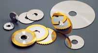
112 Index page Standard machining data.1 ecommended number of teeth.2...
113 Standard machining data Solid carbide slitting saws material coolant* Vc m / min teeth selection / cutting feed freecutting steel steel steel steel steel stainless steel heat resistant steel O / O / O / O / O / O / O / Type 111 : For low machining depth or short slots. Feed per teeth :,,** Type 1 : For deep machining or long slots. Feed per teeth :,1,1** cast iron luminium luminium titanium copper, brass, bronze thermoplastics duroplastics / O / O / O / / O / Type 11 : For machining of fragile or thin workpieces. Feed per teeth :,2,2** **according to material, thickness, and global rigidity * O = cutting oil * = mulsion * = Dry (air) with / TiCN / coating, increase data by 2%


114 I N F O ideally 2 teeth in contact too many teeth = feed too low per tooth / not enough place for the chips not enough teeth = vibration / risk of quick wearout Définition du nombre de dents en sciage mpfohlene Zähnezahl beim Sägen recommended number of teeth for sawing

115 Coating on request Type 111 Solid carbide slitting saws fine teeth DIN 17 D2 D thickness number of teeth,1,1,2 1,2 1, 1, 1, 1,, 1, 1 1,7 1, 1,9 1 1, 1 1,1 1,2 1, 1, 1, 1,7 2 1, 2 1, , 2, 2 2, 2 2 2, 2 2 2, ,

116 Coating on request Type 1 Solid carbide slitting saws large teeth DIN 1 D2 D thickness number of teeth, , , 2 2 2, 2 2 2, 2 2 2, 2 2 2, , , , , , , , , , , ,

117 Coating on request extra fine teeth,1,2,2,,,,,,7,,9 1, 1,2 2,, Type Solid carbide slitting saws ,1,1,2,2,,,,,,7,,9 1, 1,2 2,, * * * * * * * for machining of fragile or thin workpieces recommended on automatic lathes D2 D1 2 * * * * = see type number of teeth thickness number of teeth thickness *
118 Milling arbors with front clamping h Ø D2 SW h Ø D1 Ø D B max. 2 SW Type 21 right rbors for right hand rotation (front clamping with right hand thread) D1 D2 D SW B rt. N, , , 1 9, 1 211, , , 1 1, , 1 1 1, , 1 1 1, , , , h Ø D2 SW h Ø D1 Ø D SW Type 21 right rbors for very small slitting saws max. mm 1 D1,, D2,, D, 7, SW SW h Ø D2 2 Milling arbors with rear clamping h Ø D1 max. mm Ø D Type 22 rbor fo right hand rotation ( rear clamping with left hand thread ) D1,,,, 1, 1, 1, 1, D2 7 1 D ,,,, SW right D1* a 21 D1* a 21 D1* a 22 D1* a Spare parts D1* b 21 D1* b 21 D1* b 22 D1* b *Diameter D1 to be specified Type left rbor fo left hand rotation ( rear clamping with right hand thread ) D1,,, 1, D2 D , SW distance rings and 1 nut are included with each arbor

119
120 Standard machining data.2. Centering drills /.. Solid carbide micro and CSSICª drills /..7 Solid carbide WINNª drills /..9 Solid carbide THOª drills /.1 Solid carbide internal turning tools /.11. Solid carbide chamfering tools /.11. Solid carbide reamers.1 Solid carbide precision micro end mills.1.1 Solid carbide end mills.1.1 Solid carbide end mills for automatic lathes.17.1
121 Solid carbide knurling wheels.19 Knurl holders /.2.21 Tool holders /.22.2 Tool for coolant supply.2 Tool holders for TONOS DCO machines.27
122 Standard machining data Solid carbide drills Solid carbide reamers material coolant* Vc m / min Feed per rotation mm / 1 Vc m / min Feed per rotation mm / 1 freecutting steel steel steel steel steel stainless steel heat resistant steel cast iron luminium luminium titanium copper, brass, bronze thermoplastics duroplastics O / O / O / O / O / O / O / / O / O / O / / O / ,2,,1,,1,,1,,1,2,1,,1,2,,,,,2,,1,2,,,,,,,,7,,,,,,,2,,,,2,,,7,,1,,,2,,,1,,,,,7,1,,,,7,,7,,,,,,,7,1,1,1,,9,,,1,1,,,, 1 22,,1,2 1 1,1,1,2 1,1,1,1,7,1,1 1,,,1,,, 1,,,7,2,2, 2,2,2, 1 22,1,1,2 1,,1, 1,1,2, 1,1,1,2 1,1,1,2 * O = cutting oil * = mulsion * = Dry (air) with / TiCN / coating, increase data by 2%
123 Standard machining data Solid carbide precision micro end mills Solid carbide end mills material coolant* Vc m / min Feed per tooth mm / Z,21,2 1,2,9 Vc m / min Feed per tooth mm / Z freecutting steel steel steel steel steel stainless steel heat resistant steel cast iron luminium luminium titanium copper, brass, bronze thermoplastics duroplastics O / O / O / O / O / O / O / / O / O / O / / O / ,2,1,2,,1,,1,,1,,1,,1,,2,1,2,1,2,,1,,2,1,,,,,,2,,1,,1,,,2,,,2,2,,,2,,2,,1,,1,,2,,2,, ,1,,1,,1,2,1,2,1,2,1,,1,,1,,2,,1,,1,,1,,2,,2,,2,,2,,1,,1,,1,,1,,1,,,,2,,2,,2,,,,,7,,7,,,,7,2,,2,,2,,2,,2,,,,,1,,,,,,,,1,,1 * O = cutting oil * = mulsion * = Dry (air) with / TiCN / coating, increase data by 2%
124 Type 22 Centering flat drills Coating on request right D D solid carbide right Centering twist drills HSS solid carbide Type 22 D2 D D1 7 1 D HSS 227HSS 221HSS 22HSS 22MD 227MD 221MD 22MD 1 Type 2 D2 D1 2 D1 7 1 D HSS 27HSS 21HSS 2HSS 2MD 27MD 21MD 2MD 1 right NC centering drills HSS solid carbide Type 2 D D 2 2, HSS 29HSS 29HSS 29HSS 29HSS 219HSS 29HSS 229MD 22,9MD 29MD 29MD 29MD 29MD 29MD 219MD 29MD 219MD 229MD Type 2 D 1 2 D 2 2, HSS 2HSS 2HSS 2HSS 2HSS 21HSS 2HSS 22MD 22,MD 2MD 2MD 2MD 2MD 2MD 21MD 2MD 21MD 22MD
125 Coating on request left Centering flat drills solid carbide Type D D left Centering twist drills HSS solid carbide Type 1 2 D1 D D1 7 1 D HSS 17HSS 11HSS 1HSS 1MD 17MD 11MD 1MD 1 Type 11 2 D1 D2 D1 7 1 D HSS 117HSS 111HSS 11HSS 11MD 117MD 111MD 11MD 1 left NC centering drills HSS solid carbide Type D D 2 2, HSS 19HSS 19HSS 19HSS 19HSS 119HSS 19HSS 9MD,9MD 19MD 19MD 19MD 19MD 19MD 119MD 19MD 119MD 9MD Type D D 2 2, HSS 1HSS 1HSS 1HSS 1HSS 11HSS 1HSS MD,MD 1MD 1MD 1MD 1MD 1MD 11MD 1MD 11MD MD
126 Coating on request Solid carbide spot drills right Solid carbide micro drills right 1 D2 h D1 h 1 D2 h D h D2 h D1 h 2 1 D2 h D1 h 2 Type 2 Type 21 Type D2 D D2 D1 1 2 D2 D1 1, 1,7 1, 1,9 2,1 2,2 2,,,,,,7,7,,,9,9 1, 1,1 1,2 1, 1, 2, 2, 2, 2, 2, 1,7 1,9 1,9 1,9 2, 2, 2, 2,,,,,,2,2,7,7,,,,,,,,,,,,,,,,7,7,,,9,9 1, 1, 1,1 1,1 1,2 1,2 1, 1, 1, 1, 1, 1,7 1, 1,9 1, 1, 1, 1, 1, 1, 1, 1, ,,,,,,,,,, 7,1 7,1,, 9, 9, 1, 1, 1, 11,2 11,2 11, ,,,,,7,7,,,9,9 1, 1, 1,1 1,1 1,2 1,2 1, 1, 1, 1, 1, 1, 1,7 1,7 1, 1, 1,9 1,9,,, 7,,, 9, 9, 1, 1, 1 1 1, 1, 1, 1, 17, 17, 17, 17, 1, 1, 1, 1, 1, 1, 1, 1, 1, 1,
127 Coating on request Solid carbide twist drills 2 1 D h 2 1 D h 2 1 D h 2 1 D h left right CSSIC Type : 11 CSSIC Type : 21,,1,2,,,,,7,,9,,1,2,,,,,7,,9,,1,2,,,,,7,,9,,,,,,7,7,,,9,9 1, 1, 1,1 1,1 1,2 1,2 1, 1, 1, 1, 1, 1, 1,7 1,7 1, 1, 1,9 1,9 2,1 2,1 2,2 2,2 2, 2, 2, 2, 2, 2, 2, 2,7 2,7 2, 2, 2,9 2, ,,1,2,,,,,7,,9,,1,2,,,,,7,,9,,1,2,,,,,7,,9,,,,,,7,7,,,9,9 1, 1, 1,1 1,1 1,2 1,2 1, 1, 1, 1, 1, 1, 1,7 1,7 1, 1, 1,9 1,9 2,1 2,1 2,2 2,2 2, 2, 2, 2, 2, 2, 2, 2,7 2,7 2, 2, 2,9 2,
128 Coating on request 2 1 D h 2 1 D h 2 1 D h 2 1 D h right Solid carbide twist drills with progressive spiral WINN DIN 197 Type : 2 WINN DIN Type : 2,,1,2,,,,,7,,9,,1,2,,,,,7,,9 7, 7,1 7,2 7, 7, 7, 7, 7,7 7, 7,9,,1,2,,,,,7,,9 9, 9,2 9, 9, 1, 1, 11, 1 1 1, 1, 1,7 1,7 1, 1, 1,9 1,9 2,1 2,1 2,2 2,2 2, 2, 2, 2, 2, 2, 2, 2,7 2,7 2, 2, 2,9 2,9,,1,2,,,,,7,,9,,1,2,,,,,7,, ,1,2,,,,,7,,9 7, 7,1 7,2 7, 7, 7, 7, 7,7 7, 7,9,,2,, 9, 9,2 9, 9, 1, 1, 11, ,,1,2,,,,,7,,9, 1, 1, 1,7 1,7 1, 1, 1,9 1,9 2,1 2,1 2,2 2,2 2, 2, 2, 2, 2, 2, 2, 2,7 2,7 2, 2, 2,9 2,9,,1,2,,,,,7,,9,,1,2,,,,,7,,
129 Coating on request 2 1 D h 2 1 D h 2 1 D h 2 1 D h left Solid carbide twist drills with progressive spiral WINN DIN 197 Type : WINN DIN Type :,,1,2,,,,,7,,9,,1,2,,,,,7,,9 7, 7,1 7,2 7, 7, 7, 7, 7,7 7, 7,9,,2,, 9, 9,2 9, 9, 1, 1, 1, 1,7 1,7 1, 1, 1,9 1,9 2,1 2,1 2,2 2,2 2, 2, 2, 2, 2, 2, 2, 2,7 2,7 2, 2, 2,9 2,9,,1,2,,,,,7,,9,,1,2,,,,,7,, ,,1,2,,,,,7,,9, 1, 1, 1,7 1,7 1, 1, 1,9 1,9 2,1 2,1 2,2 2,2 2, 2, 2, 2, 2, 2, 2, 2,7 2,7 2, 2, 2,9 2,9,,1,2,,,,,7,,9,,1,2,,,,,7,,
130 Coating on request 2 1 D h 2 1 D h 2 1 D h 2 1 D h right Solid carbide drills with partial spiral THO DIN 197 Type : 2 THO DIN Type : 21,,1,2,,,,,7,,9,,1,2,,,,,7,,9 7, 7,1 7,2 7, 7, 7, 7, 7,7 7, 7,9,,1,2,,,,,7,,9 9, 9,2 9, 9, 1, 1, 1, 1,7 1,7 1, 1, 1,9 1,9 2,1 2,1 2,2 2,2 2, 2, 2, 2, 2, 2, 2, 2,7 2,7 2, 2, 2,9 2,9,,1,2,,,,,7,,9,,1,2,,,,,7,, ,,1,2,,,,,7,,9, 2,1 2,1 2,2 2,2 2, 2, 2, 2, 2, 2, 2, 2,7 2,7 2, 2, 2,9 2,9,,1,2,,,,,7,,9,,1,2,,,,,7,, , 11, ,1,2,,,,,7,,9 7, 7,1 7,2 7, 7, 7, 7, 7,7 7, 7,9,,2,, 9, 9,2 9, 9, 1, 1, 11,
131 Coating on request right Solid carbide internal turning tools Type 22 2 /1 /1, 2 D D Type 2 D 1 2 /1 /1, 2 1 D right Solid carbide chamfering tools Type 91 D d min D,,, 1 d min.,,7 1,2 1, Type 911 D2 1 D1 2 dmin D1 1, 2, d min.,1,1,1,1 D2 h,,,, , 7, 9111, ,
132 left Solid carbide internal turning tools Coating on request Type /1 /1 2, 2 D D /1 /1 2 Type 11, 2 D D left Solid carbide chamfering tools Type 191 D 9 9 D,, d min.,, d min. 9 9, 1 1,2 1,
133 Coating on request right Solid carbide reamers 1 2 ighthand cut, lefthand spiral Tolerance D1 Number of teeth Type 2 2,97 2,9 2,99,,H7,1,2,,1,2,,,,H7,,7,,9,97,9,99,,H7,1,2,,1,2,,,,H7,,7,,9,97,9,99 1, 1,H7 1,1 1,2 1, 1,1 1,2 1, 1, H7 1, 1,7 1, 1,9 1,97 1,9 1,99 H ,1 2,2 2, 2,7 2, 2,9 2, 2,H7 2,1 2,2 2, 2, 2,7 2, 2, D1 D1 7,97 7,9 7,99,,H7,1,2,,97,9,99 9, 9,H7 9,1 9,2 9, 9,97 9,9 9,99 1, 1,H7 1,1 1,2 1, 11,H7 1H7,97,9,99,,H7,1,2,,1,2,,,,H7,,7,,9,97,9,99,,H7,1,2,,,H7,97,9,99 7, 7,H7 7,1 7,2 7, D D1 2 1 D2 2, 2, 2, 2, 2, 2, 2, 2, 2, 2, 2, 2,,,,, D2,,,,,,,,,,,,,,,,,,,,,,,,,,,,,,,,,,,, D2,,,,,,,, 9, 9, 9, 9, 9, 9, 9, 9, 1, 1, 1, 1, 1, 1, 1, 1, 11, 1 D2,,,,,,,,,,,,,,,,,,,,,,,,,, 7, 7, 7, 7, 7, 7, 7, 7, 7, 7,
134 Coating on request right Solid carbide precision micro end mills Type 271 Type 27 extra short Z =2 D1 cut over center straight shank 2 spiral 9, h D1 +/,1,2,,,,,7,7,,9 1, 1,1 1,2 1, 1, 1, 1,7 1, 1,9 2,1 2,2 2, 2, 2, 2, 2,7 2, 2,9 2, 1 1 1, , Z =2 cut over center D1 straight shank 2 spiral 9, h D1 +/,1,2,2,,,,,7,,9 1, 1,1 1,2 1, 1, 1, 1,7 1, 1,9 2,,,,,7,9 1, 1,2 1, 1, 1, 1,9 2,1 2,2 2, 2, 2,7 2,, Type 71 Type 7 extra short Z = D1 cut over center straight shank 2 spiral 9, h D1 +/,1,,,7,7,,9 1, 1,1 1,2 1, 1, 1, 1,7 1, 1,9 2,1 2,2 2, 2, 2, 2, 2,7 2, 2, , Z = D1 cut over center straight shank 2 spiral 9, h D1 +/,1,,,,,7,,9 1, 1,1 1,2 1, 1, 1, 1,7 1, 1,9 2,2 2, 2, 2,9 2,,7,7,,9 1, 1, 1, 1, 1, 1, 1, 1, 2, 2, 2,,,,
135 right Solid carbide precision micro end mills Coating on request Type 27 ball end Type 279 ball end, extra short Z =2 cut over center 2 D1 spiral = D/2 9 D1 +/,1,,,,,7,,9 1, 1,2 1, 1, 1, 2,2 2, 2, , Z =2 cut over center 2 D1 spiral = D/2 9 D1 +/,1,2,2,,,,,7,,9 1, 1,1 1,2 1, 1, 1, 1, 2,,,,,7,9 1, 1,2 1, 1, 1, 1,9 2,1 2,2 2, 2,7, straight shank, h straight shank, h right Solid carbide end mills Type extra short Z = cut over center spiral 2 D1 sharp corner D1 +/,1 2,,,,,,, 2 7, h
136 right Solid carbide end mills Coating on request Type 21 Type 2 Type 1 Type Type 1 Type 1 Type 1 Type 1 dimensions Z=2 a= Z=2 / a= Z= a= Z= / a= Z= a= Z= a= Z= a= Z= a= D1 h1 1 D2 h 2,,,,,,, 7,, 9, 1, a D2 straight shank D1 cut over center 1 2 sharp corner Type DIN 27 K Type 7 DIN 27 2 Z= D1 cut over center 1 sharp corner D2 h D1 h1 1, 2, 2,,,,,,,,,,, 7,, 9, 1, 1,,,,,,,,,,,,,,,,, 1, 1, Z= D1 cut over center sharp corner 1 D1 h1 D2 h 1 2,,,,,,,, 1, 1,,,,,,,,, 1, D2 DIN HB D2 DIN HB
137 right Solid carbide end mills Coating on request For flat front machining Type 21 Type 1 dimensions Z=2 Z= cutovercenter spiral D1,, 1, 1 2 h Type 22 Type 2 dimensions Z=2 Z= cutovercenter spiral D1 h,,,,,,, 7,, 1, 1 Type 2 Type dimensions Z=2 Z= cutovercenter spiral D1 2,,, 7,, 1, h
138 Coating on request Solid carbide end mills for at front machining Z= D1 new Type 2 cut over center spiral,,,, Ø h, right oughing Solid carbide end mills for cames machining Z= Type D2 17 D1 cut over center,,2,,,, rt. N 1 2 h DIN HB 17 D1 cut over center,2, rt. N 1 Finishing Z= h 17 D1,2,2 rt. N Z=1 rt. N 1 h D1 1, 1, 1 2 2, 1 22, 2,
139 Coating on request Solid carbide knurling wheels Type 117 B B G standard knurls thickness bore pitch (every,1mm) ( ) B 1 / B 1 B / B B / B G G ,2, 2,2,,2,,2,,2,,2, 2,2, 2,2,,2,,2,,2,,2,, 1,, 1,, 1,, 1,, 1,, 1,2, 1,2, 1,2, 1,2 Quick knurling wheels thickness bore pitch (every,1mm) ( ) B 1 / B 1 B / B,9 1, 2 2,,2,, 1,, 1,2 Special executions on request
140 right Knurl holders Type 22 B D D B x 2 1 x 1 7 x x x x x x x x 1 1 x 1 1 x x 1 1 x x x x x x 1 x 1 x 1 x 1 1 x x x x x x
141 left Knurl holders Type B D x x 1 7 x x x x x x x x 1 1 x 1 1 x x 1 1 x x x x x x x 1 x 1 x 1 x 1 1 x D B
142 right Centering tool holders Type 2J D D x 2J1 x 2J2 x, 2J 7 x 7 1 2J71 7 x 7 1 2J72 7 x 7 1, 2J7 x 1 2J1 x 1 2J2 x 1, 2J right Type 21K Centering tool holders D 7 x 7 1 7, 21K7 7 x 7 1 7, 21K7 D x 1, 21K x 1, 21K x 1, 21K x 1, 21K 1 x 1 1 1, 21K1 1 x 1 1 1, 21K 1 x 1 1 1, 21K1 1 x 1 1 1, 21K 1 x , 21K17 x 1, 21K x 1, 21K x 1, 21K x 1, 21K x 1, 21K 1 x 1 1 1, 21K1 1 x 1 1 1, 21K1 1 x 1 1 1, 21K1 right Internal turning tool holders Type 22 D 7 x 7 1, 227 x 1, 22 x 1 1, 221 x 1 2, x 1 1 2, 22 D x 1 1, 221 x 1 2, x 1 1 2, 22 1 x 1 1 2, 22
143 Type J D left Centering tool holders D x J1 x J2 x, J 7 x 7 1 J71 7 x 7 1 J72 7 x 7 1, J7 x 1 J1 x 1 J2 x 1, J left Centering tool holders Type 11K D D 7 x K72 7 x 7 1 7, 11K7 7 x 7 1 7, 11K7 x 1 11K2 x 1, 11K x 1, 11K x 1, 11K x 1, 11K 1 x 1 1 1, 11K 1 x 1 1 1, 11K1 1 x 1 1 1, 11K 1 x , 11K17 x 1, 11K x 1, 11K x 1, 11K x 1, 11K 1 x 1 1 1, 11K1 1 x 1 1 1, 11K1 1 x 1 1 1, 11K1 left Internal turning tool holders Type D 7 x 7 1, 7 x 1, x 1 1, 1 x 1 1, 1 x 1 2, 2 1 x 1 1 2, x 1 1, 1 x 1 1, 1 x 1 2, 2 D 1 x 1 1 2, 1 x 1 1 2,
144 right Centering tool holders 1 x 1 Type 2SP 1 x 1 2 D D, 2SP, 2SP, 2SP, 2SP, 2SP, 2SP, 2SP, 2SP right Centering tool holders 1 x 1 Type 27 1 x 1 1 D 2 D, 27, 27, 27, 27 7, right Centering tool holders x Type 2 x D 7 2 D, 2, 2, 2, 2, 2 2 right Internal turning tool holders x Type 2 x 2 D 7 B B D 1 2, 1 2, 1 2, 2 2, 2 2, 2 2, 2, 2, 2,
145 Centering tool holders Type 2 D D x, x, x, x, 2K 2K 2K 2K 1 x 1 1, 1 x 1 1, 1 x 1 1, 2K 2K1 2K x 1, x 1, x 1, 2K 2K 2K Internal turning tool holders Type 22 D D x, 22 x 1, 221 x 2, x 1 1, x 1 2, 22 x 1 1, 221 x 1 2, 222 left Centering tool holders x Type 1 special NC 1 D 1 x D, 1, 1 left Centering tool holders x Type 1 special NC 1 D 1 x 1 D, 1, 1, 1, 1
146 Centering tool holders for machining on subspindle side x 1 Type 21 1 D D, 21, 21, 21, 21 1 Centering tool holders for machining on subspindle side 1 x 1 Type 2 1 x D D, 2, 2, 2, 2, 2 Type x 1 Tool holders Type D Tool for coolant supply x 1 D, 2, 2, 2, 2, 2, 2, 2, 2, 2, 2, 21, 21, 21, 21, 22, 22, 22, 22 x 1 Type 29 connection 1 1, 29 1/ 7
147 Monobloc tool holders for machine TONOS DCO 7/1 Type 2 tool reference line (1) 1 1 D, 2, 2, 2, 2 D Type 2T D (2x) D (2X), 2T, 2T, 2T, 2T Monobloc tool holders for machine TONOS DCO 1 Type 2 ligne díoutil Werkzeug Nullpunkt tool reference line (2) 1 D, 2, 2, 2, 2, 2 7 1, 21 1, 21 1, 21 1, 21 1, 21 D Type 2T D (2x), 2T, 2T, 2T, 2T D (2x) 1, 2T1 1, 2T1 1, 2T1 1, 2T1 Spacer Type 2S 2S

148
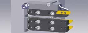
149 The advantages more tools available effi cient coolant supply system standard system compatible with other suppliers presetting on fi xed or adjustable length strong and stable clamping system easy and quick tool replacement
150 dapters available for the following machines Manufacturer Machine TYP page C / C1 M 7. K / K1 type VII M / 2 type VII / VIII M1 7. S / 1 new M1 7. KMX 2 /2 / 2 SWING 2 2 mm M1 M S1J M 7.7 S / S1 / S1 M1 7.7 SB1 SB2C () S1 / S2 / S2II S2III SV/2 new new M1 7. M1 7. M1 7.9 M1 7.9 M1 7.1 DCO 7/1 M 7.11 MICO 7 M 7.1 MICO M 7.1 DCO 1 M1 7. DCO 2/2 M1 7.1 SIGM 2/2 DT /2 new M1 M B B2 new new M2 M
151 holder TYP Section Holder page M new M M2 new Coolant and clamping supply unit Presetting device 7.27 / Spare parts
 2 K / K1 type VII M1CITIZNK1 M1 Clamping unit M1FIX1/1.")
152 Type of machine Designation Holder ccessories 7.2 Clamping unit Coolant supply unit C/C1 MCITIZNC1 M MFIX/1 MJT/1 + 2 TOOS (MX ) Type of machine Designation Holder ccessories 7.2 K / K1 type VII M1CITIZNK1 M1 Clamping unit M1FIX1/1. Coolant supply unit M1JT7/ TOOS (MX ) 1


153 Type of machine Designation Holder ccessories / 2 type VII M1CITIZN2 M1 Clamping unit included Coolant supply unit M1JT7/1 + 1 TOOS (MX 7) Type of machine Designation Holder S/1 new M1NNHW S/1 M ccessories Clamping unit Coolant supply unit M1JT7/1 + 1 TOOS (MX 7)
")
154 Type of machine Designation Holder coolant nozzle options KMX 2/2/2 SWING 22 mm M1KMX2JT M1 MJT7/1... MJT7/1.x Type of machine Designation Holder coolant nozzle options KMX 2/2/2 SWING 22 mm M1KMX2DUO M TOOS (MX 2)


155 Type of machine Designation Holder ccessories 7.2 Clamping unit Coolant supply unit S1J MSTS1J M included MJT/1 + 2 TOOS (MX ) Type of machine Designation Holder S S1 S1 M1STS1 M ccessories Clamping unit Coolant supply unit MFIX1/1 M1JT7/1 + 2 TOOS (MX ) 1


156 Type of machine Designation Holder ccessories 7.2 Clamping unit Coolant supply unit SB1 M1STSB1 M1 M1FIX1/17 M1JT7/1 + TOOS (MX ) Type of machine Designation Holder SB2C new SB2 M1STSB2 M ccessories Clamping unit Coolant supply unit M1FIX1/22 M1JT7/1 + 1 TOOS (MX 7)
 1")
 2")
157 Type of machine Designation Holder S1 S2 S2II M1STS2 M ccessories Clamping unit Coolant supply unit M1FIX1/2 M1JT7/1 + TOOS (MX 9) Type of machine Designation Holder S2III new M1ST S2III M ccessories Clamping unit Coolant supply unit M1FIX1/2 M1JT7/1 + TOOS (MX 9)


158 Type of machine Designation Holder ccessories 7.2 SV/2 M1ST SV/2 M1 Clamping unit MFIX1/2 Coolant supply unit M1JT7/1 + 2 TOOS (MX 7) 1

")
159 Type of machine Designation Holder coolant nozzle options DCO 7/1 MDCO1JT M MJT7/1... MJT7/1.x Type of machine Designation Holder coolant nozzle options DCO 7/1 MDCO1DUO M + 1 TOOS (MX 2)
160 Type of machine Designation Holder coolant nozzle options 7.2 DCO 1 M1DCO1JT M1 MJT7/1... MJT7/1.x Type of machine Designation Holder coolant nozzle options 7.2 DCO TOOS (MX 2) 1 2 M1DCO1DUO M1
161 Type of machine Designation Holder coolant nozzle options 7.2 DCO 2/2 M1DCO2JT M1 MJT7/1... MJT7/1.x Type of machine Designation Holder coolant nozzle options 7.2 DCO 2/2 M1DCO2DUO M TOOS (MX 2)
162 Type of machine Designation Holder coolant nozzle options 7.2 SIGM 2/2 M1S2JT M1 MJT7/1... MJT7/1.x Type of machine Designation Holder coolant nozzle options SIGM 2/2 M1S2DUO M1 + 1 TOOS (MX 2)


")
163 Type of machine Designation Holder ccessories 7.2 Clamping unit Coolant supply unit MICO 7 MMICO7 M included MJT/ TOOS (MX ) Parting off tool type Ma7Micro7 included Type of machine Designation Holder ccessories 7.2 Clamping unit Coolant supply unit MICO MMICO M included MJT/ TOOS (MX )


164 M2DT1T , 22 Ø 2 7, Type of machine Designation Holder coolant nozzle options DT /B DT 2/B2 origine standard M2DT2T new M2DT1T M2 M2JT7/ Type of machine Designation Holder coolant nozzle options DT /B DT 2/B2 M2DT1T M2 M2JT7/
165 . M1FIX1/2 1, M1NOMU M1JT7/1
166 . MFIX/ , MNOMU119 MJT/1
 f = fixed length a")

167 Insert holder Clamping system (fixed length and adjustable) f = fixed length a = adjustable 1. + Mf Ma new M1f 11 M2f 1. 1 M1a 11 M2a
168 Insert holder M M1 M2 rt. N rt. N rt. N For insert type... page Ma M1a M2a Mf M1f M2f TOPIN type Ma7 M1a7 M2a7 Mf7 M1f7 M2f7 TOPIN type Ma7C Mf7C TOPIN type Ma7 M1a7 M2a7 Mf7 M1f7 M2f7 TOPIN type M1a7C M1f7C TOPIN type M2a7C M2f7C TOPIN type new Ø max 1 1. MaCUT1 MfCUT1 M1aCUT1 M1fCUT1 CUTIN type CUT1 2. Ø max M2aCUT1 CUTIN type CUT1 2. Ø max MaCUT22 MfCUT22 M1aCUT22 M1fCUT22 CUTIN type CUT
169 Insert holder new Ø max M M1 M2 rt. N rt. N rt. N M2aCUT22 For insert type... CUTIN type CUT22 page MaSCC MfSCC M1aSCC M1fSCC ISOIN CC..2.. (type 11..)..1 MaSCC9 M1aSCC9 M2aSCC9 MfSCC9 M1fSCC9 M2fSCC9 ISOIN CC..9T.. (type..)..1 MaSDJC7 MfSDJC7 M1aSDJC7 M1fSDJC7 ISOIN DC (type 1..).1.19 MaSDJC11 M1aSDJC11 M2aSDJC11 MfSDJC11 M1fSDJC11 M2fSDJC11 ISOIN DC..11T.. (type 1..).1.19 MaSDNCN11 MfSDNCN11 M1aSDNCN11 M1aSDNCN11 ISOIN DC..11T.. (type 1..).1.19 MaSVJC11 M1aSVJC11 M2aSVJC11 MfSVJC11 M1fSVJC11 M2fSVJC11 ISOIN VC (type 1..).2.2 MaSVVCN11 MfSVVCN11 M1aSVVCN11 M1fSVVCN11 ISOIN VC (type 1..).2.2 Ma2 Mf2 M1a2 M1f2 COIN type
170 Insert holder right hand cut off line or left hand cutt on subspindle M M1 M2 rt. N rt. N rt. N For insert type... page MaV M1aV TOPIN type Ma7V M1a7V TOPIN type Ma7C TOPIN type Ma7V M1a7V TOPIN type () M1a7C TOPIN type new Ø max M2a7C M2aCUT1C TOPIN type 71 CUTIN type CUT
171 Insert holder right hand cut off line or left hand cutt on subspindle M M1 M2 new Ø max rt. N rt. N rt. N M2aCUT22C For insert type... CUTIN type CUT 22 page Ø max 1 1. MaCUT1V MfCUT1V M1aCUT1V M1fCUT1V CUTIN type CUT1 2. Ø max MaCUT22V MfCUT22V M1aCUT22V M1fCUT22V CUTIN type CUT MaSDJC11V M1aSDJC11V ISOIN type DC..11T.. (type 1..).1.19 MaSVJC11V M1aSVJC11V ISOIN type VC (type 1..).2.2 MaSVC11 M1aSVC11 ISOIN type VC (type 1..).2.2 Ma2V M1a2V COIN type
172 tool holder a = adjustable D 1 2 rt. N 1 Ma2 1 Ma2 1 Ma2 D 1 Ma M1a2 1 1 M1a2 1 1 M1a2 1 1 M1a M1a M2a2 1 M2a2 Knurl holder a = adjustable D B rt. N Ma22 B D 11 M1a D B 9 M2a22 D
173 Ciamping unit rt. N MFIX/1 rt. N M1FIX1/1 M1FIX1/1. M1FIX1/17 M1FIX1/2 M1FIX1/22 Coolant supply unit Connection Ø G1/ coolant nozzle /1 Ø 1. x rt. N MJT/1 Connection Ø G1/ coolant nozzle 7/1 Ø x rt. N M1JT7/1 Connection Ø G1/ Ø x coolant nozzle 7/1 rt. N M2JT7/1 Optional nozzle see page 7.2
174 coolant nozzle /1 rt. N compatible items /1 Ø 1. MJT /1 1.x /1 Ø 1. MJT /1 1.x MMICO MJT/1 a nozzle MJT /1 1.x is included with each item. /1 Ø 2.2 MJT /1 2.2x 7/1 rt. N compatible items 7/1 Ø 1. MJT 7/1 1.x 7/1 Ø 1. MJT 7/1 1.x MCITIZNC1 MDCO1JT M1DCO1JT M1DCO2JT M1S2JT M1KMX2JT M1JT7/1 M2JT7/1 7/1 2 Ø 1. MJT 7/1 1.x2 a nozzle MJT 7/1.x is included with each item. 7/1 Ø. MJT 7/1.x

175 Presetting device daptors rt. N MPST1 daptor and master gauge must be ordered separately Type Section daptator and master gauge CITIZN C / C1 ST S1J TONOS DCO 7/1 TONOS MICO 7 TONOS MICO MD1 MD2 MMST CITIZN K / K1 type VII CITIZN 1 / 2 type VII / VIII HNHW S / 1 MNUHIN KMX 2 / 2 / 2 MNUHIN SWING 2 2 mm ST S / S1 / S1 ST SB1 ST SB2C () ST S1 ST S2 / S2II /S2III ST SV / 2 TONOS DCO 2 / 2 TONOS DCO SIGM 2 M1/2D1 M1D2 M1MST TONOS DCO 1 M1DCO1D1 M1DCO1D2 M1MST TONOS DT / 2 TSUGMI B / B2 M1/2D1 M2D2 M2MST
176 spare parts setting screw rt. N MaMx. locking screw rt. N MMxT fixing screw rt. N MMx2 setting screw rt. N M1aMx. locking screw rt. N MMxT fixing screw rt. N M1/2Mx2 fixing screw rt. N M1/2Mx2

177 spare parts screws and keys for insert clamping holders M...2 VMx9T1 T1 M...2 VMx9T1 T1 M... VM2.x7.T T M... VM2.x7.T T M...7 VMx7T T M...7C VMx.T T M...7 VMx7T T M...7 VMx9T1 T1 M...7C VMx7.T1 T1 M...7 VMx9T1 T1 M...SC... VM2.x7.T T M...SC...9 VMx9T1ISO T1 M...SD...7 VM2.x7.T T M...SD...11 VMx9T1ISO T1 M...SV...11 VM2.x7.T T M / M1...CUT1 CUT1SST M2...CUT1 CUT1ST M2...CUT1C CUT1ST M / M1...CUT1V CUT1SST M / M1...CUT22 CUT22SST M2...CUT22 CUT22ST M2...CUT22C CUT22ST M / M1...CUT22V CUT22SST spare parts for ground base rt. N M2
178 Index of items J.2 11K J.22 21K F.2 2C /2D N N NOVIB SF SF SF DCO NOVIB 1. 7C 1.1 7DCO / / /1.27 7ZX C 1.1 7/7D DCO1 1. 7DCO NOVIB 1. 7Z / SF SF /1.2 7SF /1.2 7ZX S 1.2 7C 1.2 7DCO NXF 1./ /1. 71S D 1.2/1. 71S /1./1. 7ZX ZX ZX /7 1./1.1 7/7D 1. 7C 1. 7DCO Z / /1.9 71D S NXF 1./ /1.2/1. 7ZX ZX ZX /1.1 77DCO DCO /
179 Index of items CC./.1 CUT1H 2. CUT1HX 2. CUT22H 2. CUT22HX 2. CUT1H 2. CUT1HX 2. CUTGN 2. CUTTN 2.7 CUTUN 2. CUTU 2. CUTU 2. D1 1.1 D1F DC.1/.19 ISO11./.1 ISO./.1 ISO1.1/.19 ISO1.1/.19 ISO1.2/.2 ISO17.2/.2 ISO21.1/.11 ISO22.1/.11 ISO2.1/.17 ISO2.1/.17 ISO2.2/.22 ISO27.2/.21 Ma Ma7Micro7 7.1 MD 7.27 MCITIZN 7. M 7.11 Mf 7/27/2 MFIX 7.2 MJT 7.2 MMST 7.27 MMICO 7.1 MSTS1J 7.7 M1a M1/2 D 7.27 M1DCO1D 7.27 M1CITIZN 7./7. M1DCO 7./7.1 M1f M1FIX 7.2 M1HNHW 7. M1JT 7.2 M1KMX2 7. M1MST 7.27 M1S2 7.1 M1ST 7.71 M2a M2DT 7.1 M2f 7.2/7.21 M2D M2MST 7.27 M2JT 7.2 MJT 7.2 MPST S 1.1 S7 1.1 S7 1.1 SC.1/.11 SD.1.17 SV.2.22 THO.1 VC.2.2 W7 1. W71 1. W7 1. W71 1. WINN./.9 Special tools for machines CitizenCincom 7./7. Hanhwa 7. Manurhin 7. Star 7.71 Tornos Deco 1./.27/7.111 Tornos Delta 7.1 Tornos Micro 1.1/7.1 Tornos Sigma 7.1 Tsugami 7.1
180 ISO29 STM D 2 DIN1 ISO ISO292 STM D 1 F < < <1. 2
181

182
01.eps
 444 SumiTurn T-REX Tool Holders Cost reduction for copying with unique multiple cornered insert Carbide inserts, cermet inserts and 4 types of breakers are available. Expansion of our popular steel turning
F3000 SERIES FEATURES F3042 F3038 F301090 F3052 F307575 1
 OSG-WALTER Vol. 5 F3000 Series F3010 P3F90R NEW WAK25 F3000 SERIES FEATURES F3042 F3038 F301090 F3052 F307575 1 2 INSERT SIZE & APPLICABLE CUTER INSERTS APPLICATION CHART Inserts Application Chart Product
KOMET KUB K2® 小径対応ヘッド交換式ドリル
 KOMET KUB K2 Replaceable Head Drill for Tiny Diameters With this replaceable head system for the doublecutting KUB K2, KOMET has introduced an ingenious system of replaceable drill heads. These now also
メタルバンドソー
 Metal Band Saw Blades Tornado Series selection TiCN HSS Co FAX FMX PM VL Selection Chart Selection Chart Solids Selection Teeth 3 note 1) Structurals, Tubing H section steels Light gauge steels Tube 4
PRODUCT INFORMATION Highly Efficient FXS Carbide Ball Nose End Mills Vol. 3 PAT.P. FXS-EBT FXS-LS-EBT FXS-PC-EBT FXS-EBM
 PRODUCT INFORMATION Highly Efficient FXS Carbide Ball Nose End Mills Vol. 3 PAT.P. FXS-EBT FXS-LS-EBT FXS-PC-EBT FXS-EBM 3 Flutes Series Features Thanks to 3 flutes ball nose geometry, all of that reach
1 2 3
 INFORMATION FOR THE USER DRILL SELECTION CHART CARBIDE DRILLS NEXUS DRILLS DIAMOND DRILLS VP-GOLD DRILLS TDXL DRILLS EX-GOLD DRILLS V-GOLD DRILLS STEEL FRAME DRILLS HARD DRILLS V-SELECT DRILLS SPECIAL
Tornado Series selection SW TiCN HSS Co FAX VL PM
 Metal Band Saw Blades Tornado Series selection SW TiCN HSS Co FAX VL PM Selection Chart Selection Chart Solids 3 Selection Teeth 4 note 1) Structurals, Tubing H section steels Light gauge steels Tube Products
Features Features FeaturesThread milling cutters 1
 Thread Milling Cutter Series NEW SIZES Features Features FeaturesThread milling cutters 1 Threading process (view from above) CUTTER Series PLANET Machining Technique Guide to (Tool Specification) Icons
NEW AquaREVO Drills Stub/Regular AQRVDS AQRVDR
 NEW Stub/Regular AQRVDS AQRVDR NEW Stub/Regular AQRVDS AQRVDR Material, design, coating are completely all renewed, Dramatically improves all functions required for drilling New Shape New Material ong
Thread Milling Cutter Series
 Thread Milling Cutter Series Features Features FeaturesThread milling cutters 1 Planet Cutter Series Threading process (view from above) Machining Technique Guide to (Tool Specification) Icons Tool Materials
Thread Mill Series
 Thread Mill Series Index Go to the following for the quick tool search. Guide to Icons Tool Materials Helix Angle Shank Tungsten Carbide Cobalt HSS Helix angle of flute for cutters Tolerance for shank
H1-H4
 No.489 Plunging Tools SEC-PDL/ SEC - SEC-Plunge Drill PDL Type/ SEC-Plunge Mill Type Having an edge in pocketing and deep contour milling! Lineup of 10 items each from the PDL type / type! Achieving stable
LINE UP High Speed Carbide End Mills for Aluminum Alloys AERO Series AERO-EXTL For finishing 3-flute, extra long type see p.10 AERO-ETL For finishing
 AERO End Mill High Speed Carbide End Mills for Aluminum Alloys Vol.4! New cutting data on specials! LINE UP High Speed Carbide End Mills for Aluminum Alloys AERO Series AERO-EXTL For finishing 3-flute,
アクアEXオイルホールロング(CC2015).indd
.indd") High Efficiency Deep Hole Drilling D 1D 20D 2D 0D UA Drills Oil-Hole Long Non-Step drilling is possible at the hole depth of 0D High efficient drilling with long tool life with Wet and MQL Cutting edge
High Efficiency Deep Hole Drilling D 1D 20D 2D 0D UA Drills Oil-Hole Long Non-Step drilling is possible at the hole depth of 0D High efficient drilling with long tool life with Wet and MQL Cutting edge
SGドリルシリーズ_CC2015.indd
 SG Drill Series High performance PMHSS Drills High performance PMHSS Drills Powder HSS with SG Coating and the tool life is 2 times of conventional coated drills. Extremely precise positioning and Stable
PRODUCT NEWS No. 405 NEW PRODUCT 45 SSE45 series 90 SSD90 SSE45 45 JCTMA ECO PRODUCT SSD90 90 JCTMA ECO PRODUCT
 PRODUCT NEWS No. 0 NEW PRODUCT SSE series 0 SSD0 SSE JCTMA ECO PRODUCT SSD0 0 JCTMA ECO PRODUCT series SSE, SSD0 Dijet-mill SSE type SSE For general use and face milling Features SSE gives wide application
Anti-Vibration AD Bar for Internal Machining AD Feature for maximum 6 times of L/D with the advanced damper effect. By anti vibration damper effect, i
 内径 Boring ADバー AD Bar ADバー 防振機構内蔵ヘッド交換式ボーリングバー Anti-Vibration AD Bar ヘビーメタル製特殊ダンパー機構で ビビリ や 振動 を抑制 Suppressed chattering with the anti-vibration dampener ヘッド交換で 多様な加工に対応 A wide variety of internal machining
BNM
 Features and benefits 1. Ultimate precision indexable ball nose endmill with two effective teeth Radius form accuracy : below m (Radius form accuracy of insert : below m) 2. Precision clamp screw mounting
botek_8p.indd
 DEEP HOLE DRILLING SYSTEMS SOLID CARBIDE TOOLS Throw away type Deep hole drilling tools botek Type 01, 07, 07A Sole Agent MURAKI LTD. (MACHINE & TOOL DIVISION) Tokyo, Osaka, Nagoya & Fukuoka Type 01 Type
Machining Performance of High-rate Facemilling Cutters with SWC Application Tetsutaro HOSHI, Itsuro BABA and Tadai MATSUMOTO To develop milling tools
 Machining Performance of High-rate Facemilling Cutters with SWC Application Tetsutaro HOSHI, Itsuro BABA and Tadai MATSUMOTO To develop milling tools for high-rate machining of steels, prototype cutters
00_1512_SLIMLINE_BOOK.indb
 PIECE type SLIM type Imbalance value Less interference type, ideal for deep machining Ideal for drilling 2 PIECE REGULAR type Rigidity value Nozzle type When compared to the slim type, it has more rigidity
03-01 Senyouki.pdf
 Special Surface Treatment Rust-free under normal use conditions. No loss of precision due to rust. Minimum maintenance required. Stub Holder KH-E KH-EC1 Stub Holder KH-A 406 KH-E Quick Change Stub Holder
TOP-Line brochure A4-出力.indd
 トップライン TOP-ine SWISS MAD 自動旋盤 小型 CNC 旋盤用高性能ツール ライン TOP-ine トップ トップライン専用の先進テクノロジー生産ライン TOP-ine 700 INFO > 2 710 / 720 6 > 12 730 / 740 7 > 24 750 / 760 10 > 68 770 / 780 7050 / 7060 W750 / W760 > 129 CAPTO
455-omote+
 No.455 For steel industry and eavy industry Inserts and Holders or eavy duty turning SNMM Type inserts wit N and N cip reakers or Rouging RCMT Type inserts wit N Type cip reaker or cip control New coating
TURNING INERT NEW RODUCT 2014 ocket Guide
 TURNING INERT NEW RODUCT 2014 ocket Guide TURNING INERT NEW RODUCT 2014 ocket Guide TURNING INERT NEW RODUCT 2014 3 7 11 13 15 18 20 24 26 28 30 34 38 40 44 45 47 3 ocket Guide 2014 ocket Guide 2014 4
OSG Product Catalogue VOL-2.pdf
 TAPS SPIR POINTED TAP SERIES GENER APPLICATION EX-POT Suitable for through hole tapping of carbon steels, alloy steels and nonferrous metals whose chips are produced in continuous coil form. These taps
High performance PM-HSS Drills Powder HSS with SG Coating and the tool life is 2- times of conventional coated drills. Extremely precise positioning a
 SG Drill Series High performance PM-HSS Drills High performance PM-HSS Drills Powder HSS with SG Coating and the tool life is 2- times of conventional coated drills. Extremely precise positioning and Stable
OSG Product Catalogue VOL-2.pdf
 IPG CARBIDE END MILLS & DRILLS S SERIES 2 FLUTE SHORT SMG-EDS 2 FLUTE SHORT WITH PREMIER COATING TA-SMG-EDS S S 1 1.5 2.0 2.5 3.0 3.5 4.0 4.5 5.0 6.0 7.0 8.0 9.0 10.0 11.0 12.0 14.0 16.0 18.0 20.0 PRe
 Vol. A-TAP A-SFT A-POT Highly Efficient Multi-Purpose Tap Series Galling No Galling Galling No Galling Spiral Fluted Tap NEXT NEW SIZES FROM NEXT Spiral Fluted Tap FROM P.18 P.20 NEXT NEW SIZES FROM
DIN Connector_p2-25.qxd
 INDEX 1 DIN Connectors Varieties of DIN Connectors, Kinked Contact and One Touch Lock Metal Tab Kinked Contacts One Touch Lock Metal Tabs 2 Spec Sheet Soldering/Wire wrapping type Pitch Rated current 3A
02-03 HSK-AEFC.indb
 H S K 267 CTSA New Super tite-lock Milling Chuck Slim design milling chuck. Specially designed slits enables heavy endmilling. Multibore tool system 5690 13416075 HSK40A -CT16SA - 75 1 2 16 45 75 50 26
ALシリーズ.indd
 アルミ専用エンドミル 倍刃長タイプ AD- AD- NS の A シリーズは あらゆる条件で安定した高能率加工を実現 コストパフォーマンスに優れた高剛性 倍刃長タイプ NS の A シリーズは あらゆる条件で安定した高能率加工を実現 幅広い領域で安定した加工面精度が得られ 高速加工でもビビリを抑制 A-series realized a stable and high efficient machining.
WE WESB WENB WESNB 428
 KH-A-NL Quick Change Stub Tapper Designed for use on KH-A spindle. Spindle Feed: All kinds of feed styles.for spindle feed other than pitch feed, use KH-A-NL in a condition where the tension feature always
アクアドリルEX改定.indd
 AQUA Drill EX Series AQDEXS AQDEXR AQDEXOHD AQDEXOHD AQDEXOHD AQDEXZ Delivering high-performance consistently in a wide range from moderate-low to high speeds AQUA Drill EX Series AQDEXS AQDEXR AQDEXOHD
<96BC8FCC96A290DD92E82D37>
 Integrated Operation & Programming Guidance with extremely simplified operations Integrated Operation & Programming Guidance with extremely simplified operations i FANUC MANUAL GUIDE i is an integrated
Direct Motor Drive Lead Screws / Resin Lead Screw type RM / RM RM Resin Lead Screw type RM / Resin MoBo 2 MRH 2 Features A 2-phase Stepping Motor is m
 RM Resin Lead Screw typerm / Resin MoBo MRH Features A -phase Stepping Motor is mounted directly onto the shaft end of a Resin Lead Screw, which is multi-use product. Lead Screw Shaft is ideally constructed
CA55 Series Four Features 1 Bright Gold Coating PICA Physical Innovation for Coating Advantage Super Smooth Surface by Specific Surface Finish Technol
 CA55 SerieS SerieS CA55 Coated Carbide for Steel Machining Wide Application Range. Supperior Coating Technology. High Speed and High Efficiency. TZE00049 CA55 Series Four Features 1 Bright Gold Coating
 5 11 3 1....1 2. 5...4 (1)...5...6...7...17...22 (2)...70...71...72...77...82 (3)...85...86...87...92...97 (4)...101...102...103...112...117 (5)...121...122...123...125...128 1. 10 Web Web WG 5 4 5 ²
AME type Roughing End Mill AME New Product News No
 AME type Roughing End Mill AME New Product News No.1212-3 2019-4 New variations of coating, introducing AJ coating series. Nicked inserts enable suppression of chattering in heavy milling! Cutting Applications
mirror1604
 PRODUCT NEWS No.5 SERIES EXPANSION BNM typebnm-c type RNM typernm-c type MBN typembn-h type / MRN typemrn-h type MIRROR BALL MIRROR RADIUS MIRROR BALL BNM BNM-C MIRROR BALL carbide shank series are possible
 6 4 45 7ZS 5 59 7 8 94 05 4 5 6 4 5 5 6 8 8 40 45 48 56 60 64 66 66 68 7 78 80 8 7 8 0 0 0 90 0 57 64 69 66 66 69 0 4 4 4 4 4 0 7 48 5 4 4 5 4 4 4 7 46 46 6 46 8 46 48 46 46 4 46 46 4 4 5 4 6 4 9 9 0
_NC Spot Drill_muraki.indd
 NO NEED TO CHOOSE NINE9 DOES IT ALL! Cat. No. 02 NC Spot Drills Corner Rounding Cutters & Engraving Tools & i-center INDEX P1~22 P23~27 i - Center P28~34 i - Center P35~36 1 2 4 25 P13 D max. 45 0.45
コード型式タップサイズキャップ L D kg コレットプリセットドライバスパナ Code Model Tap Size Nut Collet Preset Driver Spanner BT50 -STM J 型タップ (Old JIS Taps) 105 3
 105 3") BT BT AHO HSK A/E/F/C HSK T C UTS 専用機関連機器ブシュ メントリミSTM 高さ調整式シンクロ用タップホルダ Synchronous Tap Holder With Easy Tool Length Adjustment 刃先突き出し長さの調整はホルダ外周部を回すだけで完了 Projection length of the cutting tool can be adjusted
BT BT AHO HSK A/E/F/C HSK T C UTS 専用機関連機器ブシュ メントリミSTM 高さ調整式シンクロ用タップホルダ Synchronous Tap Holder With Easy Tool Length Adjustment 刃先突き出し長さの調整はホルダ外周部を回すだけで完了 Projection length of the cutting tool can be adjusted
K02LE indd
 I Linear Stage Table of Contents 1. Features... 1 2. Description of part Number... 1 3. Maximum Speed Limit... 2 4. Specifications... 3 5. Accuracy Grade... 4 6. Motor and Motor Adaptor Flange... 4 6-1
189 2015 1 80
 189 2015 1 A Design and Implementation of the Digital Annotation Basis on an Image Resource for a Touch Operation TSUDA Mitsuhiro 79 189 2015 1 80 81 189 2015 1 82 83 189 2015 1 84 85 189 2015 1 86 87
 6 4 45 ZS7ZS4ZS 5 59 7 8 94 05 4 5 6 4 5 5 6 8 8 40 45 48 56 60 64 66 66 68 7 78 80 8 7 8 0 0 0 90 0 0 4 4 4 4 6 57 64 69 66 66 66 69 4 0 7 48 5 4 4 5 4 4 4 7 46 46 6 46 8 46 48 46 46 4 46 46 4 4 5 4
Continuous Cooling Transformation Diagrams for Welding of Mn-Si Type 2H Steels. Harujiro Sekiguchi and Michio Inagaki Synopsis: The authors performed
 Continuous Cooling Transformation Diagrams for Welding of Mn-Si Type 2H Steels. Harujiro Sekiguchi and Michio Inagaki Synopsis: The authors performed a series of researches on continuous cooling transformation
No468_1609
 高能率荒加工用工具 No.468 新製品 NEW PRODUCT QM MAX GⅡ GMX / MXG 形 QM MAX GⅡ GMX / MXG type with high efficient roughing. 高能率 効果コスト削減 Achieved high efficient & economical machining!! 新チップ材種 New insert grade / チップ厚み
止まり穴ソリッド加工 (Type01000 Type01010) 貫通穴ソリッド加工 (Type01000 Type01010) OK OK OK 止まり穴カウンター加工 (Type01000 Type01010) NG 貫通穴カウンター加工 (Type01000 Type01010) クロスホール
 貫通穴ソリッド加工 (Type01000 Type01010) OK OK OK 止まり穴カウンター加工 (Type01000 Type01010) NG 貫通穴カウンター加工 (Type01000 Type01010) クロスホール") Type01 スローアウェイタイプ Type Type01001 2 12.0017.99 1 2 0.9mm Type01000 2 18.00.99 2 2 0.9mm Type01011 Type01010 12.0017.99 18.00.99 1 2 2 2 0.9mm 0.9mm * 2 12.0017.99 21 K10K0 SP1SP91SP BBXBB 1 1.017.99 11
Type01 スローアウェイタイプ Type Type01001 2 12.0017.99 1 2 0.9mm Type01000 2 18.00.99 2 2 0.9mm Type01011 Type01010 12.0017.99 18.00.99 1 2 2 2 0.9mm 0.9mm * 2 12.0017.99 21 K10K0 SP1SP91SP BBXBB 1 1.017.99 11
Fig. 1 Schematic construction of a PWS vehicle Fig. 2 Main power circuit of an inverter system for two motors drive
 An Application of Multiple Induction Motor Control with a Single Inverter to an Unmanned Vehicle Propulsion Akira KUMAMOTO* and Yoshihisa HIRANE* This paper is concerned with a new scheme of independent
H8000操作編
 8 26 35 32H800037H800042H8000 49 55 60 72 2 3 4 48 7 72 32 28 7 8 9 5 7 9 22 43 20 8 8 8 8 73 8 13 7 7 7 55 10 49 49 13 37 49 49 49 49 49 49 12 50 11 76 8 24 26 24 24 6 1 2 3 18 42 72 72 20 26 32 80 34
March 8, 2011 March 8,
 March 8, 2011 March 8, 2011 2 March 8, 2011 3 March 8, 2011 4 4 5 March 8, 2011 March 8, 2011 2009 NCTC Report on Terrorism NCTC National Counterterrorism Center 6 2009 NCTC Report on Terrorism March 8,
2
 8 24 32C800037C800042C8000 32 40 45 54 2 3 24 40 10 11 54 4 7 54 30 26 7 9 8 5 6 7 9 8 18 7 7 7 40 10 13 12 24 22 22 8 55 8 8 8 8 1 2 3 18 11 54 54 19 24 30 69 31 40 57 23 23 22 23 22 57 8 9 30 12 12 56
LHHBAA+ArialMT Adobe Identity 0
 13ヲ ヲオヲァヲャヲ ヲアヲゥヲイ ヲウヲァヲイ ヲェヲエヲ ヲ ヲアヲュヲァヲイヲ ヲクヲイ (ヲウヲ ヲエヲカヲッヲイ 6メ2ヲ ヲエヲウヲ ヲアヲッ) 30965 2009-12-23 ICS: 93.040 1 71 71 71 7 1 71 7 1501-03-05-02-01:2009 1 71 71 71 71 71 71 71 7 TEXNIKH 1 71 71 71 71 71
 5 7 3AS40AS 33 38 45 54 3 4 5 4 9 9 34 5 5 38 6 8 5 8 39 8 78 0 9 0 4 3 6 4 8 3 4 5 9 5 6 44 5 38 55 4 4 4 4 5 33 3 3 43 6 6 5 6 7 3 6 0 8 3 34 37 /78903 4 0 0 4 04 6 06 8 08 /7 AM 9:3 5 05 7 07 AM 9
2011_NC Spot Drill_MURAKI-ok.indd
 NO NEED TO CHOOSE NINE9 DOES IT ALL! Cat. No. 01.a NC Spot Drills Corner Rounding Cutters & Engraving Tools & i-center INDEX P1~22 P23~27 i - Center P28~34 i - Center P35~36 1 2 4 25 P13 D max. 45 0.45
 6 4 4 9RERE6RE 5 5 6 7 8 9 4 5 6 4 4 5 6 8 4 46 5 7 54 58 60 6 69 7 8 0 9 9 79 0 4 0 0 4 4 60 6 9 4 6 46 5 4 4 5 4 4 7 44 44 6 44 8 44 46 44 44 4 44 0 4 4 5 4 8 6 0 4 0 4 4 5 45 4 5 50 4 58 60 57 54
 6 50G5S 3 34 47 56 63 http://toshibadirect.jp/room048/ 74 8 9 3 4 5 6 3446 4755 566 76373 7 37 3 8 8 3 3 74 74 79 8 30 75 0 0 4 4 0 7 63 50 50 3 3 6 3 5 4 4 47 7 48 48 48 48 7 36 48 48 3 36 37 6 3 3 37
 6 3 34 50G5 47 56 63 74 8 9 3 4 5 6 3446 4755 566 76373 7 37 3 8 8 3 3 74 74 79 8 30 75 0 0 4 4 0 7 63 50 50 3 3 6 3 5 4 4 47 7 48 48 48 48 7 36 48 48 3 36 37 6 3 3 37 9 00 5 45 3 4 5 5 80 8 8 74 60 39
evel egarding the Transmission apability Table 1. The values given in the table are for a service factor of 1.Using the table on the right, please mod
 NISSEI evel New Products evel gears atalog Number of NISSEI evel The catalog number systems of differs from other miter gears. 001 G F Hand of () Products Shape (Finished Shape) Surface finish () The haracteristics
2
 8 23 32A950S 30 38 43 52 2 3 23 40 10 33 33 11 52 4 52 7 28 26 7 8 8 18 5 6 7 9 8 17 7 7 7 38 10 12 9 23 22 22 8 53 8 8 8 8 1 2 3 17 11 52 52 19 23 29 71 29 41 55 22 22 22 22 22 55 8 18 31 9 9 54 71 44
Photo. 1. Scale banding in roughing mill work roll. Photo. 2. Etched micro-structure of alloyed grain iron roll. Photo. 3. Etched micro-structure of a
 Work Rolls in Hot Strip Mills Hidemaro KAWAHARA Synopsis: The work roll materials in hot strip mills and the damages of rolls which arise in rolling operation are discussed in this paper. As for the rolls
高能率 多機能タップ A-TAP Vol.10 新価格体系 New Price 2018 年 6 月 Highly Efficient Multi-Purpose Tap Series タップホルダ シンクロマスター SynchroMaster 追加 New tap holder SynchroMa
 高能率 多機能タップ A-TAP Vol.10 新価格体系 New Price 2018 年 6 月 Highly Efficient Multi-Purpose Tap Series タップホルダ シンクロマスター SynchroMaster 追加 New tap holder SynchroMaster INDEX A-TAP is A-TAP Features 3 Cutting Conditions
Connectors for Automobiles 62 SEALED SERIES Japanese English
 Connectors for Automobiles 62 SEALED SERIES Japanese English 62 P-01 62 P-02 ( ) ( ) ( ) ( ) 0.6 24.6 ( ) ( ) ( ) ( ) 2.5 20.8 2.1 M(1400-0434) F(1400-0432) ( ) ( ) ( ) ( ) 0.6 24.6 ( ) ( ) ( ) ( ) 2.5
form
 MST Slot Mill MST Type Full range from 1.mm to 23.3mm in three types. For narrow groove Self-clamping type MSTA Slot Width For middle groove Groove width semi-adjustable type Slot Width For wide groove
タップ総合
 1 2 3 4 N NEW タップシリーズ N Tap series ねじ加工に適した高バナジウムハイスの使用により 汎用タップながらも長寿命 高剛性設計で安定ねじ加工を実現 Nスパイラルタップ NSP By using high vanadium HSS, which is suitable for cutting screw threads, even flexibility screw threads
080906_…o…−…^…b…vVSCW
 Thyristor Type Single-Phase Power Regulator 2030 A 6A 150200A TOKYO RIKOSHA CO., LTD Latest VARITAP VSCW Series Achieved 1/2 the width (our company comparison). Free Power source of 100 to 240V specification.cover-type
xEffect_SG_MV_Part2_E_xEffect_SG_MV_E
 Miniature Circuit Breakers FAZ-NA, FAZ-RT, FAZ-DU SG56912 FAZ-NA/-RT/-DU According to UL 489, CSA C22.2 No. 5 and also IEC 60947-2 standard For Applications, wich are permitted for UL 1077 or CSA C22.2
2 3 12 13 6 7
 2 8 17 42ZH700046ZH700052ZH7000 28 43 54 63 74 89 2 3 12 13 6 7 3 4 11 21 34 63 65 8 17 4 11 4 55 12 12 10 77 56 12 43 43 13 30 43 43 43 43 10 45 14 25 9 23 74 23 19 24 43 8 26 8 9 9 4 8 30 42 82 18 43
ーリングチャックMilling Chuck コレットホルダCollet Holder イドロチャックHydraulic Chuck シュリンカーチャックShrink Fit タッピングチャックTapping Chuck アーバー類Arbors マルチボアツーリングMultibore tool sys
 ーリングチャックMilling Chuck コレットホルダCollet Holder イドロチャックHydraulic Chuck シュリンカーチャックShrink Fit タッピングチャックTapping Chuck アーバー類Arbors マルチボアツーリングMultibore tool system 機能付きホルダFunction Holder プルスタッドRetention Stud シャンク規格Tool
H1-H4.ai
 PRODUCT NEWS No. 44 FU INEUP NEW TA-EZ TEZD "Indexable EZ DRI" TEZD type JCTMA 213-6 ECO PRODUCT 超硬工具協会 (JCTMA) 環境認定製品です "Indexable EZ DRI" achieved easy assembly and high cutting performance. Indexable
切削工具 NEW SUPER DRILL (Standard Head Type) 特徴 FEATURES P MT - MAX- MORSE TAPER SHANK SET (Standard) 1. 標準ヘッド ( E 以上のセット内容にはセンタードリル 替刃は含まれておりません )
 特徴 FEATURES P MT - MAX- MORSE TAPER SHANK SET (Standard) 1. 標準ヘッド ( E 以上のセット内容にはセンタードリル 替刃は含まれておりません )") 切削工具 ニュースーパードリルセット標準形ヘッド替刃 ( 標準形ヘッド用 ) ニュースーパードリルセット平形ヘッド替刃 ( 平形ヘッド用 ) エクステンションアーバ ( 標準形ヘッド専用 ) オイルリングオイルプラグ,158 159 160,161 162 162 1 1 NEW SUPER DRILL (Standard Head Type) BLADE (For Standard Head) NEW
切削工具 ニュースーパードリルセット標準形ヘッド替刃 ( 標準形ヘッド用 ) ニュースーパードリルセット平形ヘッド替刃 ( 平形ヘッド用 ) エクステンションアーバ ( 標準形ヘッド専用 ) オイルリングオイルプラグ,158 159 160,161 162 162 1 1 NEW SUPER DRILL (Standard Head Type) BLADE (For Standard Head) NEW
jjspm
 J. Jpn. Soc. Powder Powder Metallurgy Vol. 63, No. 4 157 1 * 2 3 1 639-1080 22 2 581-0854 3-167 3 572-8530 18-8 Tool Wear of Sintered Cubic Boron Nitride Compact in Cutting High-Nickel Alloy with High-Pressure
スモールツール Small Tools 3次元シャープエッジブレーカシリーズ Molded sharp edge chipbreakers Series 自動盤用 3次元シャープエッジブレーカシリーズ 3D Sharp Edge Chipbreaker Series for Automatic La
 スモールツール Small Tools 次元シャープエッジシリーズ Molded sharp edge chipbreakers Series 自動盤用 次元シャープエッジシリーズ D Sharp Edge Chipbreaker Series for Automatic Lathe 切りくず処理の悩みを解決する充実のレパートリー シリーズとの組み合わせで長寿命加工が可能 Extensive product
DIJET - Carbide Holders.pdf
 PRODUCT NEWS No. 07 B FU INEUP Fits all major manufacturers Straight Neck type 5 Items Taper Neck type Items Staight Arbor type Items Different type carbide shank holder from M to M bore diameters with
No488_1804
 PRODUCT S No. 488 SERIES EXPANSION Spot facing drill Spot facing drill with point angle of 180 (flat face). Size range: 1-14mm dia. JCTMA 2015-018 ECO PRODUCT Flat Face Application Spot facing slope Spot
/ Motor Specifications Direct Motor Drive Ball Screws / Precision Ball Screw type MB / MB MB Precision Ball Screw type MB / MoBo C3 5 5 Features A 5-p
 / Motor Specifications MB Precision Ball Screw type MB / MoBo C3 5 5 Features A 5-pahse Stepping Motor is mounted directly onto the shaft end of a C3 grade precision Ball Screw, which is suitable for high
2
 8 23 26A800032A8000 31 37 42 51 2 3 23 37 10 11 51 4 26 7 28 7 8 7 9 8 5 6 7 9 8 17 7 7 7 37 10 13 12 23 21 21 8 53 8 8 8 8 1 2 3 17 11 51 51 18 23 29 69 30 39 22 22 22 22 21 56 8 9 12 53 12 56 43 35 27
2
 8 22 19A800022A8000 30 37 42 49 2 3 22 37 10 11 49 4 24 27 7 49 7 8 7 9 8 5 6 7 9 8 16 7 7 7 37 10 11 20 22 20 20 8 51 8 8 9 17 1 2 3 16 11 49 49 17 22 28 48 29 33 21 21 21 21 20 8 10 9 28 9 53 37 36 25
 5 30 B36B3 4 5 56 6 7 3 4 39 4 69 5 56 56 60 5 8 3 33 38 45 45 7 8 4 33 5 6 8 8 8 57 60 8 3 3 45 45 8 9 4 4 43 43 43 43 4 3 43 8 3 3 7 6 8 33 43 7 8 43 40 3 4 5 9 6 4 5 56 34 6 6 6 6 7 3 3 3 55 40 55
高能率 多機能タップ A-TAP Vol.9 Highly Efficient Multi-Purpose Tap Series
 高能率 多機能タップ A-TAP Vol.9 Highly Efficient Multi-Purpose Tap Series INDEX A-TAP is A-TAP Features 3 Cutting Conditions 5 Cutting Data 7 A-SFT for Blind Holes Metric Screw Thread A-SFT 15 (1.5P1P) Short Chamfer
アクアドリルシリーズ
 AQUA Drill Series EX Standard of high efficiency drilling and highly accurate drilling AQUA drill EX, enter the stage Realize high speed/high efficiency drilling with new flutes geometry and AQUA coating,
一般用 TiCN スパイラルタップ Symbol:SFT-TiCN TiCN Coated Spiral Fluted Tap TiN コーティングに比べ対磨耗性 反溶着性に優れ軟質材から硬質材まで幅広く使用できます (TiCN coating has a good welding resistan
 スパイラルタップ シリーズ Spiral Fluted Tap Series 一般用スパイラルタップ ( ネック付きタイプ ) Symbol:SFT / SFT-OX Spiral Fluted Tap For General Application (Neck Type) 1. 止まり穴用 1. For Blind Holes. 2. 切りくずが コイルのようにカールして排出される被 2. Materials
 Safety Performance of Steel Deck Plate (Flat Decks) Used for Concrete Slab Moulding CONTENTS 1. Introduction ---------------------------------------------------------------- (2) 2. Flat Decks ------------------------------------------------------------------
名称未設定-1
 切削工具 ニュースーパードリルセット標準形ヘッド NEW SUPER DRILL (Standard Head Type) 特徴 FEATURES P.31-34 モールステーパシャンクセット ( 標準タイプ ) MT - MAX- D MORSE TAPER SHANK SET (Standard) 1. 標準ヘッド ( E 以上のセット内容にはセンタードリル 替刃は含まれておりません ) ø L3
銅電極の加工に圧倒的な長寿命と高品位を実現する銅電極加工用ロングネックボールエンドミル DRB230 Realize long life and high quality in machining copper electrode. Long Neck Ball End Mill for Coppe
 銅電極の加工に圧倒的な長寿命と高品位を実現する銅電極加工用ロングネックボールエンドミル DRB230 Realize long life and high quality in machining copper electrode. Long Neck Ball End Mill for Copper Electrode - DRB230. バリを最小限に抑えた高精度な加工を可能にするシャープな刃形状!
<8B5A8F70985F95B632936EE7B22E696E6464>
 47 Electrical Discharge Truing for Electroplated Diamond Tools Koji Watanabe Hisashi Minami Hatsumi Hiramatsu Kiyonori Masui (211 7 8 ) Electroplated diamond tools are widely used for grinding because
 Influence of Material and Thickness of the Specimen to Stress Separation of an Infrared Stress Image Kenji MACHIDA The thickness dependency of the temperature image obtained by an infrared thermography
Z7000操作編_本文.indb
 2 8 17 37Z700042Z7000 46Z7000 28 42 52 61 72 87 2 3 12 13 6 7 3 4 11 21 34 61 8 17 4 11 4 53 12 12 10 75 18 12 42 42 13 30 42 42 42 42 10 62 66 44 55 14 25 9 62 65 23 72 23 19 24 42 8 26 8 9 9 4 11 18
製品パンフ
 HAMA TOOL A RELIABLE TOOL MAKER IN PURSUIT OF EXCELLENCE P R O D U C T C A T A L O G "HAMA TOOL" enabling to make various tooling Tools which have been designed and manufactured by HAMA TOOL are contributing
磁気測定によるオーステンパ ダクタイル鋳鉄の残留オーステナイト定量
 33 Non-destructive Measurement of Retained Austenite Content in Austempered Ductile Iron Yoshio Kato, Sen-ichi Yamada, Takayuki Kato, Takeshi Uno Austempered Ductile Iron (ADI) 100kg/mm 2 10 ADI 10 X ADI
19_22_26R9000操作編ブック.indb
 8 19R900022R900026R9000 25 34 44 57 67 2 3 4 10 37 45 45 18 11 67 25 34 39 26 32 43 7 67 7 8 7 9 8 5 7 9 21 18 19 8 8 70 8 19 7 7 7 45 10 47 47 12 47 11 47 36 47 47 36 47 47 24 35 8 8 23 12 25 23 OPEN
A Study on Throw Simulation for Baseball Pitching Machine with Rollers and Its Optimization Shinobu SAKAI*5, Yuichiro KITAGAWA, Ryo KANAI and Juhachi
 A Study on Throw Simulation for Baseball Pitching Machine with Rollers and Its Optimization Shinobu SAKAI*5, Yuichiro KITAGAWA, Ryo KANAI and Juhachi ODA Department of Human and Mechanical Systems Engineering,
OSG_BIT
 Characteristics Quality starts with consistent tooling -Insist on OSG bits that elivers precision tooling with harness, consistency an maximum torsion strength meeting the market nees. OSG bits FIBER FOW
How to read the marks and remarks used in this parts book. Section 1 : Explanation of Code Use In MRK Column OO : Interchangeable between the new part
 Reservdelskatalog MIKASA MT65H vibratorstamp EPOX Maskin AB Postadress Besöksadress Telefon Fax e-post Hemsida Version Box 6060 Landsvägen 1 08-754 71 60 08-754 81 00 info@epox.se www.epox.se 1,0 192 06
LM35 高精度・摂氏直読温度センサIC
 Precision Centigrade Temperature Sensors Literature Number: JAJSB56 IC A IC D IC IC ( ) IC ( K) 1/4 55 150 3/4 60 A 0.1 55 150 C 40 110 ( 10 ) TO-46 C CA D TO-92 C IC CA IC 19831026 24120 11800 ds005516
How to read the marks and remarks used in this parts book. Section 1 : Explanation of Code Use In MRK Column OO : Interchangeable between the new part
 Reservdelskatalog MIKASA MVB-85 rullvibrator EPOX Maskin AB Postadress Besöksadress Telefon Fax e-post Hemsida Version Box 6060 Landsvägen 1 08-754 71 60 08-754 81 00 info@epox.se www.epox.se 1,0 192 06
無標題-1
 Professional cranes & hoists for lifting SOFT START/STOP Reduction Gear Motor CHENG DAY MACHINERY WORKS CO., LTD. No. 173, Wen Chiu Road, Dajia District, Taichung City, 37 Taiwan. Tel: +88--288-1581 Fax:
How to read the marks and remarks used in this parts book. Section 1 : Explanation of Code Use In MRK Column OO : Interchangeable between the new part
 Reservdelskatalog MIKASA MVC-50 vibratorplatta EPOX Maskin AB Postadress Besöksadress Telefon Fax e-post Hemsida Version Box 6060 Landsvägen 1 08-754 71 60 08-754 81 00 info@epox.se www.epox.se 1,0 192
Nachi - AQDEX
 The next generation solid carbide drill Series Series AQDEX AQDEXR AQDEXOH3D AQDEXOH5D AQDEXOH8D 3D 5D Realize stable, high efficiency drilling in wide area, from medium and low speed up to high speed