DVIOUT-soturon
|
|
|
- はすな なぐも
- 5 years ago
- Views:
Transcription
1 PIC/CPLD
2 1 4 2 PIC MPLAB IDE CCSC LED LCD UART PCB CAD DRC
3 LED MATRIX LED UART LED LCD UART LED UART LED LED LED ( ) 107 3
4 1 PIC (Peripheral Interface Controller) CLPD PIC 4
5 2 PIC Microchip Technology Co. PIC 2.1 PIC I/O LED 2.2 PIC 1. PIC10 PIC12 12bit 2. PIC16 14bit A/D PIC18 16bit 2.3 PIC 5
6 Windows XP Home Edition Ver 2002 Service Pack 2 MPLAB IDE CCSC PIC AKI-PIC Ver 3.5 PIC Ver MPLAB IDE CCSC MPLAB IDE Windows Microchip Technology Co. CCSC CCS PICmicro MCU PIC C 6


7 3 LED 3.1 PIC16F628 4 **H**M**S** **M**S**** 2 LED 1 1: LED 7
8 Reserve memory area initialization START Timer1 STOP LED CONT Initialize variables main loop goto START Reset switch? Timer1 start letgo flag? letgo flag = 1 goto START LED CONT 2: LED PIC I/O Timer1 Stop LED CONT Reset START Reset letgo (=0x00 ) START (0x01 ) Timer1 letgo LED CONT START 8
9 LED CONT Mode switch? hyoji 0x00 hyoji 0x01 Serect factor Wreg Display data Convert Display data to LED data keta < 8 PortB LED data 1m Sec Wait Stop bottom check PortB 0xFF Increment keta return 3: LED LED CONT Mode High hyoji 0x00 **H**M**S** Low hyoji 0x01 **M**S**** 8 keta < 8 Warking Regester( Wreg) LED PortB 1 milli second?? START PortB 0xFF keta 9
10 Save register from TMR1? Count up Recover register 4: LED (Wreg Status regester) Timer1 10
11 3.3 5 LED Tr Tr PortA 0,1,2 3bit 74HC138 PortB LED 15mA LED 1V R R = (3 1) = 13 3 ; 130 [Ω] 5: LED 11


12 4 LCD 4.1 TZ-250A 6 6: LCD 12
13 LED PIC TMR1 LCD 500m Sec LCD 1 LCD LED / SS Low gogoch gogo 0x05 B letgo SS letgo letgo SS SS letgo A letgo B 13
14 Reseive memory area Initialization Timer 1 stop Reset HIGH Initialize LCD units 500mSec wait Reset LOW 500mSec wait Set LCD initial value Display routine First display Main routine A TMR 1 STOP B Start/Stop botton check Set gogoch flag gogo 0x05 Idle loop Initialize time variables Display routine goto B Reset = 0? TMR1 start letgo = 1 Start/Stop button Display routine letgo=1? goto A goto B 7: LCD 14
15 8 gogoch gogo LCD bit 855µSec Step 4bit 15
16 0 1 2 gogo = Display Display from 1 10 Sec only Sec to end Display from 1 Sec to end Display from 10 Sec to end Display from 1 Min to end Display all Get display code Convert display code into LCD code Make and output lower 4 digit code A Strobe HIGH LCD Busy = 1 Wait Strobe LOW gogoch = 1? Wait 855 µ Sec LCD Busy = 1 Wait goto next time digit had send upper 4 digits? Make and output upper 4 digit code goto A return 8: LCD 16
17 Save regester Set gogoch flag Increment gogo Count up Recover regester 9: LCD gogoch gogo 17
18 4.3 LCD 10: LCD PortA HC138 74LS251 LCD PortA 0 2 PortB 18

19 5 5.1 MR-999 PIC16F628A UART( ) AM-RT5 AM-HRR3 AM C C : 19


20 : 20
21 STX ETX 8bit STX Initialization Define variables Get unit code Make send data A Make send data B Send STX Main loop Send STX Send data A Send data B Send data A Send data B Send ETX 13: 21
22 MODE 2bit RA 4,5 RB 2 UART AM-RT5 UART PB1 14: 22

23 V TA7291P 6V 15: 23
24 state idle UART data state state idle ( STX) STX state wait STX wait idle state ready1 ready1 data STX STX data ( ETX) state idle ETX STX data data1 state ready2 ready2 data STX ETX data data2 state compare1 data STX ETX compare1 ready1 data1 data state compare2 compare2 compare1 data2 data1 data2 state ready1 17 data Elbow, Shoulder, Wrist 24
25 Initialization Get unit code state idle Get Receive data Receive error idle data = STX? state wait Receive error Main loop RS232 ERRORS? wait ready1 data = STX? data = STX? state ready1 Receive error data = ETX? state idle Save data as data1 state ready2 state = ready2 data = STX or ETX? Receive error Save data as data2 state compare1 compare1 data = data1? state compare2 Receive error Make Motor drive code compare2 data = data2? code match? Motor drive state ready1 Receive error 16: 25
26 Grip data = default Stop Reverse Run Stop (Elbow, Shoulder, Wrist) Base data = default Stop Reverse Run Stop 17: V PIC 78L05 5V 26
27 18: 27

28 : PIC AD ADC LM C 1000 C PIC Vref V 10bit OP ADC 0 0 LM35 ADC Set Wait ADC 28
29 Initialization Set ADC ch 0 Wait Get ADC ch 0 data Fine adjust data Set ADC ch 1 Display ch 0 data Get ADC ch 1 Set ADC ch 0 data 5 7or=1020? Indefinate Fine adjust data Display ch1 data Get ch 0 data Mode? Fine adjust data Set ADC ch 2 Display ch 0 data Main loop Get ADC ch 2 Set ADC ch 0 data 5 7or=1020? Indefinate Fine adjust data Display ch2 data Get ch 0 data Fine adjust data Wait 20: 29
30 ADC Mode True ADC ADC 0 1 (Indefinate) UART MIN 1 Sec CCP UART 10mSec 6 1mSec 625kbps 1.5µSec High 1.5µSec SA MOS FET 2SJ
31 21: 31

32 22: UART MOS ( 23) ( 24) ( 25) running routine 1mSec CCP CCP UART 1 Display Main Loop LCD 100 0xA 0xD 0xC 0xB 60bit


33 23: MOS FET 24: 33

34 25: Initialization Set up CCP enable Grobal interrupt disable CCP interrupt enable CCP interrupt Main Loop Start is pushed? running routine Reset is pushed? Stop button check Now running? ClearNumberdata Display flag? Display 26: 34
")
35 27: PCB CAD DRC Trax Maker mm DC-DC MCP1252 PVA OHP Tracs Maker Design Rule Check(DRC) Clearance Net list 35
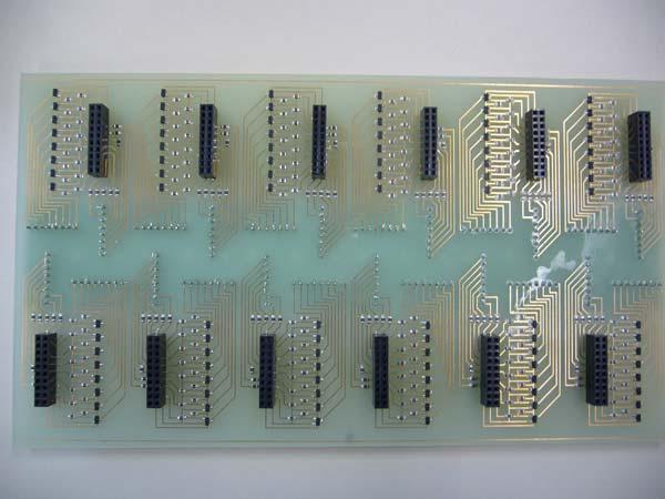
36 28: UART LED MATRIX LED MATRIX LED LED PIC CPLD CPLD UART 31 LED UART LED LED Circuit Maker Trax Maker PCB Netlist ( 34) 36

37 29: PCB 37


38 30: LED MATRIX 31: LED MATRIX 3 38

39 32: LED 33: LED 39
40 34: 100mil CPLD UEW( ) UEW 40


41 35: LED 36: LED 41

42 8.1.3 UART 37: UART CPLD 1 6V 5V 3V CPLD LED CPLD 5V CPLD Low 2.5V kΩ UART 10MHz LED CPLD kHz
43 38: LED MATRIX 43
44 40 0xA 41 0xD 42 0x5 0x5 39: A bit 44
45 40: A 41: D 45
![42: 5 [1] PIC16F [2] C PIC [3]](/docs-images/91/105983734/images/46-0.jpg "VHDL [4] VHDL CPLD [5] PIC/CPLD")
46 42: 5 [1] PIC16F [2] C PIC [3] VHDL [4] VHDL CPLD [5] PIC/CPLD 46
47 9 47
48 10 LED ;******************************************************** ; ; StopWatch ; ;******************************************************** list p=pic16f648a include P16F648A.inc ;**************** Label Definition ******************* c10h equ h 20 ;Counter adr (10th hour) c01h equ h 21 ;Counter adr (1st hour) c10m equ h 22 ;Counter adr (10th min) c01m equ h 23 ;Counter adr ( 1st min) c10s equ h 24 ;Counter adr (10th sec) c01s equ h 25 ;Counter adr ( 1st sec) c1000 equ h 26 ;Counter adr (1000th sub-sec) c100 equ h 27 ;Counter adr (100th sub-sec) c10 equ h 28 ;Counter adr (10th sub-sec) c001 equ h 29 ;Counter adr (1st sub-sec) hyoji equ h 2a ;0 -> --h--m--s-- / 1 -> --m--s---- temp equ h 2b ;Adjust waiting time running equ h 30 pushed equ h 31 ;0 -> pushed, 1 -> release chnum equ h 32 pushch equ h 33 relech equ h 34 letgo equ h 35 keta equ h 3a ;display position 0~7 bcd_in equ h 3b ;display substance seg7_0 equ b ;Pattern 0 seg7_1 equ b ;Pattern 1 seg7_2 equ b ;Pattern 2 seg7_3 equ b ;Pattern 3 seg7_4 equ b ;Pattern 4 seg7_5 equ b ;Pattern 5 48
49 seg7_6 equ b ;Pattern 6 seg7_7 equ b ;Pattern 7 seg7_8 equ b ;Pattern 8 seg7_9 equ b ;Pattern 9 seg70 equ h 40 ;Pattern 0 set address seg71 equ h 41 ;Pattern 1 set address seg72 equ h 42 ;Pattern 2 set address seg73 equ h 43 ;Pattern 3 set address seg74 equ h 44 ;Pattern 4 set address seg75 equ h 45 ;Pattern 5 set address seg76 equ h 46 ;Pattern 6 set address seg77 equ h 47 ;Pattern 7 set address seg78 equ h 48 ;Pattern 8 set address seg79 equ h 49 ;Pattern 9 set address w_save equ h 4a ;W Register save adr s_save equ h 4b ;STATUS Register save adr CNT1 equ h 4c ;1m sec conter address CNT2 equ h 4d ;1m sec conter address ;**************** Program Start *********************** org 0 ;Reset Vector goto init org 4 ;Interrupt Vector goto int ;**************** Initial Process ********************* init bcf status, rp0 movlw h 07 movwf cmcon ;All digital bsf status, rp0 ;Change to Bank1 movlw b ;RA012 out / RA345 in movwf trisa ;Set PORTA clrf trisb ;RB all out movlw b ;not RBPU/TOCS/PSA=0,PS=111 movwf option_reg ;Set OPTION_REG movlw b ;CCP1IE -ON 49
50 movwf pie1 bcf status, rp0 ;Change to Bank0 movlw 0xff movwf portb ;Set OFF all 7seg movlw b movwf intcon ;PEIE-ON / GIE-OFF movlw b movwf ccp1con ;compare mode Spcial event trigger movlw 0x01 movwf ccpr1h movlw 0xF4 movwf ccpr1l ;compare = 0.2u*500 = 100u Sec clrf t1con ;TMR1:prescaler 1:1 not use clrf tmr1h clrf tmr1l movlw seg7_0 ;Set 7segment pattern 0 movwf seg70 ;Save pattern 0 movlw seg7_1 ;Set 7segment pattern 1 movwf seg71 ;Save pattern 1 movlw seg7_2 ;Set 7segment pattern 2 movwf seg72 ;Save pattern 2 movlw seg7_3 ;Set 7segment pattern 3 movwf seg73 ;Save pattern 3 movlw seg7_4 ;Set 7segment pattern 4 movwf seg74 ;Save pattern 4 movlw seg7_5 ;Set 7segment pattern 5 movwf seg75 ;Save pattern 5 movlw seg7_6 ;Set 7segment pattern 6 movwf seg76 ;Save pattern 6 movlw seg7_7 ;Set 7segment pattern 7 movwf seg77 ;Save pattern 7 movlw seg7_8 ;Set 7segment pattern 8 movwf seg78 ;Save pattern 8 50
51 movlw seg7_9 ;Set 7segment pattern 9 movwf seg79 ;Save pattern 9 ;************* Timer stand-by Process ***************** stand_by clrf c10h clrf c01h clrf c10m clrf c01m clrf c10s clrf c01s clrf c1000 clrf c100 clrf c10 clrf c001 clrf running clrf letgo clrf pushed clrf tmr1h clrf tmr1l ;Clear just in case ; movlw 0 ; movwf c10h ; movlw 0 ; movwf c01h ; movlw 0 ; movwf c10m ; movlw 0 ; movwf c01m ; movlw 0 ; movwf c10s ; movlw 0 ; movwf c01s ; movlw 0 ; movwf c1000 ; movlw 0 ; movwf c100 ; movlw 0 ; movwf c10 51
52 ; movlw 0 ; movwf c01 ;If you want to change initial display, change here loopin bcf intcon, gie bcf t1con, 0 ;TMR 1 STOP clrf tmr1h clrf tmr1l ;Clear just in case hloop call led_cont ;Call LED Countrol sub btfsc porta, 4 goto go ;reset check clrf c10h clrf c01h clrf c10m clrf c01m clrf c10s clrf c01s clrf c1000 clrf c100 clrf c10 clrf c001 goto hloop ;************** Timer start Process ******************* go btfss letgo, 0 goto loopin bsf intcon, gie ;Interruption enable bsf t1con, 0 ;TMR1 start loop call led_cont ;Call LED Countrol sub btfss letgo, 0 goto loopin goto loop ;************* 1msec Timer Subroutine ***************** wait movlw 0x04 movwf cnt2 52
53 t1m2 movlw 0xF2 movwf cnt1 timloop nop decfsz cnt1, f goto timloop decfsz cnt2, f goto t1m2 return ;************ Bottom Check ************************* checkin movlw 9 movwf chnum clrf pushch clrf relech btfsc running, 0 goto stopchk btfss pushed, 0 goto Lcheck1_stop ; L goto Hcheck1_stop ; H Lcheck1_stop btfsc porta, 3 return goto LinL_stop LinL_stop bcf pushch, 0 rlf pushch, f Lcheck2_stop decfsz chnum goto Lcheck1_stop movf pushch, w btfsc status, z bsf pushed, 0 bsf letgo, 0 return Hcheck1_stop btfsc porta, 3 goto HinH_stop 53
54 return HinH_stop bsf relech, 0 rlf relech, f goto Hcheck2_stop Hcheck2_stop decfsz chnum goto Hcheck1_stop movlw 0xff subwf relech, w btfss status, z return bcf pushed, 0 bsf running, 0 return ;********************************** stopchk btfss pushed, 0 goto Lcheck1_run ; L goto Hcheck1_run ; H Lcheck1_run btfsc porta, 3 return goto LinL_run LinL_run bcf pushch, 0 rlf pushch, f Lcheck2_run decfsz chnum goto Lcheck1_run movf pushch, w btfsc status, z bsf pushed, 0 bcf letgo, 0 return Hcheck1_run btfsc porta, 3 goto HinH_run return 54
55 HinH_run bsf relech, 0 rlf relech, f goto Hcheck2_run Hcheck2_run decfsz chnum goto Hcheck1_run movlw 0xff subwf relech, w btfss status, z return bcf pushed, 0 bcf running, 0 return ;************ Begin Interruption Process ************** int movwf w_save ;Save W register movf status,w ;Read STATUS reg movwf s_save ;Save STATUS reg bcf status,rp0 ;Change to Bank0 btfss pir1, ccp1if goto int_end ;*********** Interruption routine by ccp1if ************** count incf c001, f movlw 10 subwf c001, w ;freg - wreg -> wreg btfss status, z goto int_end ;10 0 -> clrf c001 incf c10, f movlw 10 subwf c10, w btfss status, z goto int_end clrf c10 incf c100, f movlw 10 subwf c100, w 55
56 btfss status, z goto int_end clrf c100 incf c1000, f movlw 10 subwf c1000, w btfss status, z goto int_end clrf c1000 incf c01s, f movlw 10 subwf c01s, w btfss status, z goto int_end clrf c01s incf c10s, f movlw 6 subwf c10s, w btfss status, z goto int_end clrf c10s incf c01m, f movlw 10 subwf c01m, w btfss status, z goto int_end clrf c01m incf c10m, f movlw 6 subwf c10m, w btfss status, z goto int_end clrf c10m incf c01h, f movlw 10 subwf c01h, w btfss status, z goto int_end clrf c01h 56
57 incf c10h, f movlw 10 subwf c10h, w btfss status, z goto int_end clrf c10h ;************ END of Interruption Process ************** int_end bcf pir1, ccp1if ;Clear interrupt flag movf s_save,w ;Read saved STATUS reg movwf status ;Recover STATUS reg swapf w_save,f ;Read saved W register swapf w_save,w ;Recover W register retfie ;***************************************************** ;************** LED Control Subroutine ************* ;***************************************************** led_cont btfss porta, 5 ;mode switch check goto type2 ;type2:2ndmode type1 clrf hyoji ;--h--m--s-- clrf keta ;HC138-Q0:L ; movf keta, w movwf porta movf c10h, w movwf bcd_in call bcd_7seg call wait call checkin movlw h ff movwf portb incf keta, f ; movf keta, w movwf porta movf c01h, w 57
58 movwf bcd_in call bcd_7seg call wait call checkin movlw h ff movwf portb incf keta, f ; movf keta, w movwf porta movf c10m, w movwf bcd_in call bcd_7seg call wait call checkin movlw h ff movwf portb incf keta, f ; movf keta, w movwf porta movf c01m, w movwf bcd_in call bcd_7seg call wait call checkin movlw h ff movwf portb incf keta, f ; movf keta, w movwf porta movf c10s, w movwf bcd_in call bcd_7seg call wait call checkin movlw h ff movwf portb 58
59 incf keta, f ; movf keta, w movwf porta movf c01s, w movwf bcd_in call bcd_7seg bcf portb, 7 ;dot call wait call checkin movlw h ff movwf portb incf keta, f ; movf keta, w movwf porta movf c1000, w movwf bcd_in call bcd_7seg call wait call checkin movlw h ff movwf portb incf keta, f ; movf keta, w movwf porta movf c100, w movwf bcd_in call bcd_7seg call wait call checkin movlw h ff movwf portb return ; type2 movlw h 01 ;--m--s---- movwf hyoji 59
60 clrf keta ;HC138-Q0:L ; movf keta, w movwf porta movf c10m, w movwf bcd_in call bcd_7seg call wait call checkin movlw h ff movwf portb incf keta, f ; movf keta, w movwf porta movf c01m, w movwf bcd_in call bcd_7seg call wait call checkin movlw h ff movwf portb incf keta, f ; movf keta, w movwf porta movf c10s, w movwf bcd_in call bcd_7seg call wait call checkin movlw h ff movwf portb incf keta, f ; movf keta, w movwf porta movf c01s, w movwf bcd_in 60
61 call bcd_7seg bcf portb, 7 ;dot call wait call checkin movlw h ff movwf portb incf keta, f ; movf keta, w movwf porta movf c1000, w movwf bcd_in call bcd_7seg call wait call checkin movlw h ff movwf portb incf keta, f ; movf keta, w movwf porta movf c100, w movwf bcd_in call bcd_7seg call wait call checkin movlw h ff movwf portb incf keta, f ; movf keta, w movwf porta movf c10, w movwf bcd_in call bcd_7seg call wait call checkin movlw h ff movwf portb 61
62 incf keta, f ; movf keta, w movwf porta movf c001, w movwf bcd_in call bcd_7seg call wait call checkin movlw h ff movwf portb return ; bcd_7seg movlw seg70 addwf bcd_in, w movwf fsr movf indf, w movwf portb return end 62
63 11 LCD ;******************************************************** ; ; LCD TZ250A Stop Watch ; ;******************************************************** list p=pic16f628a include P16F628A.inc config _xt_osc & _wdt_off & _pwrte_off & _boden_of& _mclre_off & _cp_off & _lvp_off ;**************** Label Definition ******************* c10m equ h 20 ;Counter adr (10th min) c01m equ h 21 ;Counter adr (1st min) c10s equ h 22 ;Counter adr (10th sec) c01s equ h 23 ;Counter adr (1st sec) c10 equ h 24 ;Counter adr (10th sub-sec) c01 equ h 25 ;Counter adr (100th sub-sec) t0tmp equ h 26 ;TMR0 work1 equ h 27 ; work2 equ h 28 w_save equ h 30 ;W Register save adr s_save equ h 31 ;STATUS Register save adr gogo equ h 32 running equ h 33 pushed equ h 34 chnum equ h 35 pushch equ h 36 rerech equ h 37 letgo equ h 38 first equ h 39 gogoch equ h 3A d10m d01m equ h 40 equ h 41 63
64 d10s d01s d10 d01 equ h 42 equ h 43 equ h 44 equ h 45 segch blight equ h 46 equ h 47 seg_code equ h 48 ;**************** Program Start *********************** org 0 ;Reset Vector goto init org 4 ;Interrupt Vector goto int ;**************** Initial Process ********************* init bcf status, rp0 movlw h 07 movwf cmcon ;All digital bsf status, rp0 ;Change to Bank1 movlw b ;RA012 out / RA345 in movwf trisa ;Set PORTA movlw b movwf trisb ;RB6 in others out movlw b ;not RBPU/TOCS/PSA=0,PS=111 movwf option_reg ;Set OPTION_REG movlw b ;CCP1IE -ON movwf pie1 movlw 200 movwf pr2 bcf status, rp0 ;Change to Bank0 bsf portb, 5 ;RESET->ON movlw b movwf intcon ;PEIE-ON / GIE-OFF movlw b movwf ccp1con ;compare mode, special event trigger movlw 0x27 movwf ccpr1h movlw 0x10 64
65 movwf ccpr1l ;compare = 1u*10000 = 10mSec clrf t1con ;TMR1:pre1:1 not use clrf tmr1h clrf tmr1l ;tmr1 reset clrf c10m clrf c01m clrf c10s clrf c01s clrf c10 clrf c01 clrf gogo clrf gogoch clrf letgo ; Reset bsf portb, 5 ;RESET->ON movlw 8 movwf t0tmp clrf tmr0 reset_wait1_1 bcf intcon, t0if reset_wait1_2 btfss intcon, t0if goto reset_wait1_2 decfsz t0tmp, f goto reset_wait1_1 ;500mSecWait bcf portb, 5 ;RESET ->Low movlw 8 movwf t0tmp clrf tmr0 reset_wait2_1 bcf intcon, t0if reset_wait2_2 btfss intcon, t0if goto reset_wait2_2 decfsz t0tmp, f goto reset_wait2_1 ;500m Sec Wait ; bsf status, rp0 ;Bank1 movlw b
66 movwf option_reg ;prescaler 1:4 bcf status, rp0 ;Bank0 movlw 0xA1 movwf d10m movlw 0x96 movwf d01m movlw 0xA5 movwf d10s movlw 0xA5 movwf d01s movlw 0xB0 movwf d10 movlw 0xC6 movwf d01 ;initial display movlw 1 movwf first movlw 5 movwf gogo ; bsf gogoch, 0 movlw 0x01 movwf segch movlw 0x00 movwf blight ;00,FF movlw 0xE0 movwf seg_code ; dokokara ikimasuka? dokokara? btfss gogoch, 0 return clrf gogoch clrf porta movf gogo, w btfsc status, z goto keta0.01 ;1/100 movf gogo, w sublw 1 btfsc status, z goto keta0.1 ;1/10 movf gogo, w 66
67 sublw 2 btfsc status, z goto keta01s ;1Sec movf gogo, w sublw 3 btfsc status, z goto keta10s ;10Sec movf gogo, w sublw 4 btfsc status, z goto keta01m ; Min ; min keta10m btfsc first, 0 goto keta10m_2 movf c10m, w call tenkai movwf d10m ; keta10m_2 movlw 0 movwf porta movf d10m, w ;d01 andlw b ; 4bit movwf portb ; bsf portb, 4 ;strobe high busylp_d10m btfss portb, 6 ;busy high goto busylp_d10m bcf portb, 4 ;strobe low bcf intcon, t0if ;TMR0 flag clear movlw 42 movwf tmr0 ;TMR0 count 42 clear t0lp1_d10m btfss intcon, t0if ;855u sec wait goto t0lp1_d10m btfss portb, 6 ;check busy clear goto highb_d10m busyc1_d10m btfsc portb, 6 ;busy low 67
68 goto busyc1_d10m highb_d10m swapf d10m, w ; andlw b ; 4bit movwf portb ; bsf portb, 4 ;strobe high busylp2_d10m btfss portb, 6 ;busy high goto busylp2_d10m bcf portb, 4 ;strobe low bcf intcon, t0if ;TMR0 flag clear movlw 42 movwf tmr0 ;TMR0 count 42 clear t0lp2_d10m btfss intcon, t0if ;855u sec wait goto t0lp2_d10m btfss portb, 6 ;check busy clear goto keta01m busyc2_d10m btfsc portb, 6 ;busy low goto busyc2_d10m ; min keta01m btfsc first, 0 goto keta01m_2 movf c01m, w call tenkai movwf d01m keta01m_2 movlw 1 movwf porta movf d01m, w andlw b movwf portb bsf portb, 4 busylp_d01m btfss portb, 6 goto busylp_d01m bcf portb, 4 68
69 bcf intcon, t0if movlw 42 movwf tmr0 t0lp1_d01m btfss intcon, t0if goto t0lp1_d01m btfss portb, 6 goto highb_d01m busyc1_d01m btfsc portb, 6 goto busyc1_d01m highb_d01m swapf d01m, w andlw b movwf portb bsf portb, 4 busylp2_d01m btfss portb, 6 goto busylp2_d01m bcf portb, 4 bcf intcon, t0if movlw 42 movwf tmr0 t0lp2_d01m btfss intcon, t0if goto t0lp2_d01m btfss portb, 6 goto keta10s busyc2_d01m btfsc portb, 6 goto busyc2_d01m ; Sec keta10s btfsc first, 0 goto keta10s_2 movf c10s, w call tenkai movwf d10s keta10s_2 69
70 movlw 2 movwf porta movf d10s, w andlw b movwf portb bsf portb, 4 busylp_d10s btfss portb, 6 goto busylp_d10s bcf portb, 4 bcf intcon, t0if movlw 42 movwf tmr0 t0lp1_d10s btfss intcon, t0if goto t0lp1_d10s btfss portb, 6 goto highb_d10s busyc1_d10s btfsc portb, 6 goto busyc1_d10s highb_d10s swapf d10s, w andlw b movwf portb bsf portb, 4 busylp2_d10s btfss portb, 6 goto busylp2_d10s bcf portb, 4 bcf intcon, t0if movlw 42 movwf tmr0 t0lp2_d10s btfss intcon, t0if goto t0lp2_d10s btfss portb, 6 goto keta01s busyc2_d10s 70
71 btfsc portb, 6 goto busyc2_d10s ; Sec keta01s btfsc first, 0 goto keta01s_2 movf c01s, w call tenkai movwf d01s keta01s_2 movlw 3 movwf porta movf d01s, w andlw b movwf portb bsf portb, 4 busylp_d01s btfss portb, 6 goto busylp_d01s bcf portb, 4 bcf intcon, t0if movlw 42 movwf tmr0 t0lp1_d01s btfss intcon, t0if goto t0lp1_d01s btfss portb, 6 goto highb_d01s busyc1_d01s btfsc portb, 6 goto busyc1_d01s highb_d01s swapf d01s, w andlw b movwf portb bsf portb, 4 busylp2_d01s btfss portb, 6 goto busylp2_d01s 71
72 bcf portb, 4 bcf intcon, t0if movlw 42 movwf tmr0 t0lp2_d01s btfss intcon, t0if goto t0lp2_d01s btfss portb, 6 goto keta0.1 busyc2_d01s btfsc portb, 6 goto busyc2_d01s ; /10 keta0.1 btfsc first, 0 goto keta0.1_2 movf c10, w call tenkai movwf d10 keta0.1_2 movlw 4 movwf porta movf d10, w andlw b movwf portb bsf portb, 4 busylp_d10 btfss portb, 6 goto busylp_d10 bcf portb, 4 bcf intcon, t0if movlw 42 movwf tmr0 t0lp1_d10 btfss intcon, t0if goto t0lp1_d10 btfss portb, 6 goto highb_d10 busyc1_d10 72
73 btfsc portb, 6 goto busyc1_d10 highb_d10 swapf d10, w andlw b movwf portb bsf portb, 4 busylp2_d10 btfss portb, 6 goto busylp2_d10 bcf portb, 4 bcf intcon, t0if movlw 42 movwf tmr0 t0lp2_d10 btfss intcon, t0if goto t0lp2_d10 btfss portb, 6 goto keta0.01 busyc2_d10 btfsc portb, 6 goto busyc2_d10 ; /100 keta0.01 btfsc first, 0 goto keta0.01_2 movf c01, w call tenkai movwf d01 keta0.01_2 movlw 5 movwf porta movf d01, w andlw b movwf portb bsf portb, 4 busylp_d01 btfss portb, 6 goto busylp_d01 73
74 bcf portb, 4 bcf intcon, t0if movlw 42 movwf tmr0 t0lp1_d01 btfss intcon, t0if goto t0lp1_d01 btfss portb, 6 goto highb_d01 busyc1_d01 btfsc portb, 6 goto busyc1_d01 highb_d01 swapf d01, w andlw b movwf portb bsf portb, 4 busylp2_d01 btfss portb, 6 goto busylp2_d01 bcf portb, 4 bcf intcon, t0if movlw 42 movwf tmr0 t0lp2_d01 btfss intcon, t0if goto t0lp2_d01 btfss portb, 6 goto segments busyc2_d01 btfsc portb, 6 goto busyc2_d01 ; segments btfss segch, 0 goto seg_end movf blight, f btfss status, z ;Z flag -> goto seg_off 74
75 seg_on movlw 3 addwf seg_code, f goto seg_1min seg_off movlw 3 subwf seg_code, f seg_1min comf blight, f movlw 1 movwf porta movf seg_code, w andlw b movwf portb bsf portb, 4 seg_busylp_1min btfss portb, 6 goto seg_busylp_1min bcf portb, 4 bcf intcon, t0if movlw 42 movwf tmr0 seg_t0lp1_1min btfss intcon, t0if goto seg_t0lp1_1min btfss portb, 6 goto seg_highb_1min seg_busyc1_1min btfsc portb, 6 goto seg_busyc1_1min seg_highb_1min swapf seg_code, w andlw b movwf portb bsf portb, 4 seg_busylp2_1min btfss portb, 6 goto seg_busylp2_1min bcf portb, 4 75
76 bcf intcon, t0if movlw 42 movwf tmr0 seg_t0lp2_1min btfss intcon, t0if goto seg_t0lp2_1min btfss portb, 6 goto seg_1sec seg_busyc2_1min btfsc portb, 6 goto seg_busyc2_1min seg_1sec movlw 3 movwf porta movf seg_code, w andlw b movwf portb bsf portb, 4 seg_busylp_1sec btfss portb, 6 goto seg_busylp_1sec bcf portb, 4 bcf intcon, t0if movlw 42 movwf tmr0 seg_t0lp1_1sec btfss intcon, t0if goto seg_t0lp1_1sec btfss portb, 6 goto seg_highb_1sec seg_busyc1_1sec btfsc portb, 6 goto seg_busyc1_1sec seg_highb_1sec swapf seg_code, w andlw b movwf portb bsf portb, 4 seg_busylp2_1sec 76
77 btfss portb, 6 goto seg_busylp2_1sec bcf portb, 4 bcf intcon, t0if movlw 42 movwf tmr0 seg_t0lp2_1sec btfss intcon, t0if goto seg_t0lp2_1sec btfss portb, 6 goto seg_end seg_busyc2_1sec goto seg_busyc2_1sec seg_end clrf segch first_check btfss first, 0 return clrf first ; Idle Loop loop_in bcf intcon, gie ; bcf t1con, 0 ;TMR1STOP clrf tmr1h clrf tmr1l ; clrf gogo Idle call checkin btfsc porta, 4 goto go ;reset check bsf gogoch, 0 movlw 5 movwf gogo clrf c10m clrf c01m clrf c10s clrf c01s clrf c10 clrf c01 77
78 call dokokara? goto Idle go btfss letgo, 0 goto Idle bsf intcon, gie ;Interruption enable bsf t1con, 0 ;TMR1 start loop call checkin call dokokara? btfss letgo, 0 goto loop_in goto loop ; Button Check checkin movlw 9 movwf chnum clrf pushch clrf rerech btfsc running, 0 goto stopchk btfss pushed, 0 goto Lcheck_stop ; L goto Hcheck_stop ; H Lcheck_stop btfsc porta, 3 return bcf pushch, 0 rlf pushch, f decfsz chnum goto Lcheck_stop movf pushch, w btfss status, z return bsf pushed, 0 bsf letgo, 0 return Hcheck_stop btfss porta, 3 78
79 return bsf rerech, 0 rlf rerech, f decfsz chnum goto Hcheck_stop movlw 0xff subwf rerech, w btfss status, z return bcf pushed, 0 bsf running, 0 return stopchk btfss pushed, 0 goto Lcheck_run ; L goto Hcheck_run ; H Lcheck_run btfsc porta, 3 return bcf pushch, 0 rlf pushch, f decfsz chnum goto Lcheck_run movf pushch, w btfss status, z return bsf pushed, 0 bcf letgo, 0 return Hcheck_run btfss porta, 3 return bsf rerech, 0 rlf rerech, f decfsz chnum goto Hcheck_run movlw 0xff subwf rerech, w 79
80 btfss status, z return bcf pushed, 0 bcf running, 0 return ; Interrupt int movwf w_save ;Save W register movf status,w ;Read STATUS reg movwf s_save ;Save STATUS reg bcf status,rp0 ;Change to Bank0 btfsc pir1, ccp1if goto count ;ccp1if count goto int_end ;*********** Interruption routine by ccp1if ************** count bcf pir1, ccp1if ; bsf gogoch, 0 ; dokokara? incf c01, f movlw 10 subwf c01, w ;freg - wreg -> wreg btfss status, z goto int_end ;10 0 -> clrf c01 ;0 ->10 -> incf gogo incf c10, f ;*** movlw 10 subwf c10, w btfss status, z goto int_end clrf c10 incf gogo incf c01s, f ;*** bsf segch, 0 movlw 10 subwf c01s, w btfss status, z goto int_end clrf c01s 80
81 incf gogo incf c10s, f ;*** movlw 6 subwf c10s, w btfss status, z goto int_end clrf c10s incf gogo incf c01m, f ;*** movlw 10 subwf c01m, w btfss status, z goto int_end clrf c01m incf gogo incf c10m, f ;*** movlw 10 subwf c10m, w btfss status, z goto int_end clrf c10m goto int_end ;************ END of Interruption Process ************** int_end movf s_save,w ;Read saved STATUS reg movwf status ;Recover STATUS reg swapf w_save,f ;Read saved W register swapf w_save,w ;Recover W register retfie ; Sub Rutine tenkai movwf work1 movlw 8 subwf work1, w movlw b btfsc status, c movlw b movwf work2 movlw b
82 andwf iorwf return work1, w work2,w end 82
83 12 #include<16f628a.h> #fuses HS,NOWDT,PUT,NOPROTECT,NOMCLR,NOLVP,NOBROWNOUT #use delay(clock = ) #use rs232(baud = 2400, XMIT = PIN_B2, RCV = PIN_B1) #use fast_io(a) #use fast_io(b) // #define STX 0x02 #define ETX 0x03 /////Main///// void main(void) { setup_comparator(nc_nc_nc_nc); set_tris_a(0xff); set_tris_b(0xf9); port_b_pullups(true); setup_uart(true); //Main Loop while(1) { unsigned int a_data, a_data_1, b_data, b_data_1, code; code = ((~input_a()) & 0x30) + 0x10; a_data = code; a_data_1 = ((~input_b()) & 0x08); a_data = a_data_1; a_data_1 = ((~input_b()) & 0x01) << 2; a_data = a_data_1; a_data_1 = ((~input_a()) & 0x03); a_data = a_data_1; b_data = 0x40; b_data_1 = (~input_b()) & 0x30; 83
84 b_data = b_data_1; b_data_1 = ((~input_a()) & 0x0c); b_data = b_data_1; b_data_1 = ((~input_b()) & 0xc0) >> 6 ; b_data = b_data_1; putc(stx); putc(stx); putc(a_data); putc(b_data); putc(a_data); putc(b_data); putc(etx); // delay_ms(200); // } } 84
85 13 #include<16f628a.h> #fuses HS,NOWDT,PUT,NOPROTECT,NOMCLR,NOLVP,NOBROWNOUT #use delay(clock = ) #use rs232(baud = 2400, XMIT = PIN_B2, RCV = PIN_B1, PARITY = N, ERRORS) #use fast_io(a) #use fast_io(b) #byte PORTA = 0x05 #byte PORTB = 0x06 // #define STX 0x02 #define ETX 0x03 #define idle 0 #define wait 1 #define ready1 2 #define ready2 3 #define compare1 4 #define compare2 5 // char state, code, data1, data2; // void RcvErr(void); void motor_cont(char mt1, char mt2, char mt3, char mt4, char mt5); void RcvState(char data); /////Main///// void main(void) { char data; // setup_comparator(nc_nc_nc_nc); set_tris_a(0x30); //RA4,5 input 85
86 set_tris_b(0x02); port_b_pullups(false); setup_uart(true); //RB1 input output_a(0); output_b(0); code = (~PORTA & 0x30) + 0x10; //device code state = idle; } while(1) { data = getc(); if (( RS232_ERRORS & 0x06 ) == 0) RcvState(data); else RcvErr(); } void RcvErr(void) { state = idle; RS232_ERRORS = 0; } void RcvState(char data) { char motor1, motor2, motor3, motor4, motor5; switch(state) { case idle: if (data == STX) state = wait; else RcvErr(); break; case wait: if(data == STX) state = ready1; 86
87 else RcvErr(); break; case ready1: if(data!= STX) { if (data == ETX) state = idle; else { data1 = data ; state = ready2; } } break; case ready2: if (data == STX data == ETX) RcvErr(); else { data2 = data; state = compare1; } break; case compare1: if (data!= data1) RcvErr(); //A data else state = compare2; break; case compare2: if (data!= data2) RcvErr(); //B data else { if ((data1 & 0xF0) == code) { motor1 = (data1 & 0x0C) >> 2; motor2 = data1 & 0x03; motor3 = (data2 & 0x30) >> 4; motor4 = (data2 & 0x0C) >> 2; motor5 = data2 & 0x03; } } } motor_cont(motor1, motor2, motor3, motor4, motor5); state = ready1; } break; default: break; 87
88 void motor_cont(char mt1, char mt2, char mt3, char mt4, char mt5) { switch(mt1) { case 0: output_low(pin_a2); output_low(pin_a3); break; case 1: output_high(pin_a2); output_low(pin_a3); break; case 2: output_low(pin_a2); output_high(pin_a3); break; default: output_low(pin_a2); output_low(pin_a3); } switch(mt2) { case 0: output_low(pin_b0); output_low(pin_b3); break; case 1: output_high(pin_b0) output_low(pin_b3); break; case 2: output_low(pin_b0); output_high(pin_b3); break; default: output_low(pin_b0); output_low(pin_b3); 88
89 } switch(mt3) { case 0: output_low(pin_b5); output_low(pin_b4); break; case 1: output_high(pin_b5); output_low(pin_b4); break; case 2: output_low(pin_b5); output_high(pin_b4); break; default: output_low(pin_b5); output_low(pin_b4); } switch(mt4) { case 0: output_low(pin_a0); output_low(pin_a1); break; case 1: output_high(pin_a0); output_low(pin_a1); break; case 2: output_low(pin_a0); output_high(pin_a1); break; default: output_low(pin_a0); output_low(pin_a1); } 89
90 } switch(mt5) { case 0: output_low(pin_b7); output_low(pin_b6); break; case 1: output_high(pin_b7); output_low(pin_b6); break; case 2: output_low(pin_b7); output_high(pin_b6); break; default: output_low(pin_b7); output_low(pin_b6); } 90
91 14 #include <16F819.h> #fuses INTRC_IO,NOWDT,PUT,NOPROTECT,NOMCLR,NOLVP,NOBROWNOUT #device ADC=10 #use delay(clock = ) #use fast_io(b) #use fast_io(a) #include "lcd_drive.c" static float situ_data; static float cap_data; static float cam_data; void indefinite() { lcd_cmd(0xc0); printf(lcd_data, " indefinite "); } void disp_cap() { lcd_cmd(0xc0); printf(lcd_data, "CA+ = %4.0f DegC ",cap_data); } void disp_cam() { lcd_cmd(0xc0); printf(lcd_data, "CA- = %4.0f DegC ",cam_data); } void main() { setup_oscillator(osc_4mhz); setup_adc_ports(an0_an1_an2_an4_vss_vref); setup_adc(adc_clock_div_8); set_tris_a(0x3f); 91
92 set_tris_b(0x00); lcd_init(); lcd_clear(); set_adc_channel(0); //analog LM35 delay_us(50); situ_data = read_adc(); situ_data = situ_data * ; while(1) { if(input(pin_a5)) //Plus thermo mode { set_adc_channel(1); lcd_cmd(0x80); printf(lcd_data, "LM35 = %2.1f DegC ",situ_data); //display LM35 thermo cap_data = read_adc(); //get AD set_adc_channel(0); if(cap_data <= 7 cap_data >=1020) indefinite(); else{ cap_data = 0.887*cap_data+54.5; //convert AD to Theremo disp_cap(); } disp_cap(); situ_data = read_adc(); situ_data = situ_data * ; } else //Minus thermo mode { set_adc_channel(2); lcd_cmd(0x80); printf(lcd_data, "LM35 = %2.1f DegC ",situ_data); //display LM35 thermo 92
93 } cam_data = read_adc(); //get AD set_adc_channel(0); if((cam_data <= 77) (cam_data >1000)) indefinite(); else if((cam_data > 78) && (cam_data <= 377)){ cam_data = *cam_data-7.0; disp_cam(); } else if((cam_data > 377) && (cam_data <= 1000)){ cam_data = *cam_data*cam_data *cam_data-72.0; disp_cam(); } disp_cam(); situ_data = read_adc(); situ_data = situ_data * ; } delay_ms(500); } 93
94 15 UART #include <16F628A.h> #fuses HS,NOWDT,NOPROTECT,NOMCLR,NOLVP,NOBROWNOUT #use delay(clock = ) #use rs232(baud = , xmit = PIN_B2, rcv = PIN_B1) #use fast_io(b) #use fast_io(a) #define ST PIN_B3 #define RES PIN_B0 #define LED PIN_A3 #define RW PIN_A1 #define rs PIN_A2 #define str PIN_A0 static int trans_table[16] = {0x55, 0x57, 0x5D, 0x5F, 0x75, 0x77, 0x7D, 0x7F, 0xD5, 0xD7 0xDD, 0xDF, 0xF5, 0xF7, 0xFD, 0xFF}; struct counter_mix { int digit; //[0] : 1/100 [1] : 1/10 [2] : 1sec [3] : 10sec int num; //[4] : 1min [5] : 10min }time[6]; int count0001 = 0; int trans_dig = 0; short disp_flag; void lcd_out(int code, int flag) { output_b(code); output_low(rw); if (flag == 0) output_high(rs); else output_low(rs); output_high(str); delay_cycles(3); output_low(str); output_high(rw); } 94
95 void lcd_data(int asci) { lcd_out(asci, 0); lcd_out(swap(asci), 0); delay_us(50); } void lcd_cmd(int cmd) { lcd_out(cmd, 1); lcd_out(swap(cmd), 1); delay_us(50); } void lcd_clear() { lcd_cmd(0x01); delay_ms(20); } void lcd_init() { delay_ms(15); lcd_out(0xff, 1); delay_ms(5); lcd_out(0x30, 1); delay_ms(1); lcd_out(0x30, 1); delay_ms(1); lcd_out(0x20, 1); delay_ms(1); lcd_cmd(0x2e); //fanc set DL=4 lcd_cmd(0x08); //Disp off lcd_cmd(0x0c); //Disp on cursol [off] brink [off] lcd_cmd(0x06); //Entry Mode set lcd_clear(); } 95
96 void disp() { disp_flag = 0; lcd_cmd(0xc0); printf(lcd_data, "%d%d:%d%d;%d%d", time[5].num, time[4].num, time[3].num, time[2].num, time[1].num, time[0].num); } #int_ccp1 void tmr1_ccp_isr() { ++count0001; if(count0001 > 9){ ++(time[0].num); disp_flag = 1; count0001 = 0; if(time[0].num > 9){ ++time[1].num; time[0].num = 0; if(time[1].num > 9){ ++time[2].num; time[1].num = 0; if(time[2].num > 9){ ++time[3].num; time[2].num = 0; if(time[3].num > 5){ ++time[4].num; time[3].num = 0; } } if(time[4].num > 9){ ++time[5].num; time[4].num = 0; } 96
97 } } } putc(trans_table[10]); // A delay_us(35); putc(trans_table[13]); // D delay_us(35); putc(trans_table[time[trans_dig].num+1]); //Number 0-9 delay_us(35); putc(trans_table[12]); // C delay_us(35); putc(trans_table[11]); // B delay_us(35); putc(trans_table[time[trans_dig].digit+1]); //digit trans_dig; } if(trans_dig > 5) trans_dig = 0; void main() { int i; short release, condition; delay_ms(100); //condition TRUE = run,false = stop //release FALSE = pushed // for(i = 0 ; i < 6 ; i++){ time[i].digit = i; //1/100 : [0]...10m : [5] time[i].num = 0; //data initialize } release = TRUE; condition = FALSE; port_b_pullups(true); setup_timer_1(t1_internal t1_div_by_1); 97
98 setup_ccp1(ccp_compare_reset_timer); CCP_1 = 0x1388; set_tris_a(0x00); set_tris_b(0x0f); output_low(led); lcd_init(); lcd_clear(); lcd_cmd(0x80); printf(lcd_data, "STOP WATCH"); lcd_cmd(0xc0); printf(lcd_data, "00:00;00"); set_uart_speed(625000); //625k pbs disable_interrupts(int_ccp1); enable_interrupts(global); while(1) { if(!(input(st)) && release){ //Start/Stop check delay_ms(20); if(!(input(st)) && (condition == FALSE)){ set_timer1(0x0000); ENABLE_INTERRUPTS(INT_CCP1); condition = TRUE; release = FALSE; } else if(!(input(st)) && (condition == TRUE)){ DISABLE_INTERRUPTS(INT_CCP1); condition = FALSE; release = FALSE; } } if(!(input(res)) && release){ delay_ms(20); 98
99 } } if(!(input(res)) && (condition == FALSE)){ for(i = 0 ; i < 6 ; i++) time[i].num = 0; count0001 = 0; release = FALSE; set_timer1(0x0000); lcd_cmd(0xc0); printf(lcd_data, "reset!!!"); delay_ms(1000); lcd_cmd(0xc0); printf(lcd_data, "00:00;00 "); } } if(input(st)){ //release check delay_ms(30); if(input(st)) release = TRUE; } if(disp_flag == 1) disp(); 99
100 16 LED UART library IEEE; use IEEE.STD_LOGIC_1164.ALL; use IEEE.STD_LOGIC_ARITH.ALL; use IEEE.STD_LOGIC_UNSIGNED.ALL; -- Uncomment the following lines to use the declarations that are -- provided for instantiating Xilinx primitive components. --library UNISIM; --use UNISIM.VComponents.all; entity UART is Port ( RxD : in std_logic; -- Read 10 bit data RESET : in std_logic; F10M : in std_logic; -- Main Clock Digit_sel : out std_logic_vector(5 downto 0); -- Display unit select Number : out std_logic_vector(3 downto 0) -- Transmit data ); end UART; architecture RTL of UART is signal RxD0 : std_logic; signal RxShiftReg : std_logic_vector(8 downto 0); signal Detect_counter : std_logic_vector(3 downto 0); signal Num_of_catch : std_logic_vector(3 downto 0); signal Data_ready : std_logic; signal Fst_start_bit : std_logic; signal Detect_start : std_logic; signal Go_to_next : std_logic; signal Framing_err : std_logic; signal Read_Digit : std_logic; signal Read_Number : std_logic; signal pre_read_number : std_logic; signal pre_read_digit : std_logic; signal keep_data : std_logic_vector(3 downto 0); signal one_check : std_logic_vector(3 downto 0); signal idigit_sel : std_logic_vector(5 downto 0); signal inumber : std_logic_vector(3 downto 0); begin process (F10M, RESET) begin if(reset = 0 ) then RxD0 <= 0 ; RxShiftReg <= (others => 0 ); Detect_counter <= (others => 0 ); Num_of_catch <= (others => 0 ); Data_ready <= 0 ; Fst_start_bit <= 0 ; Detect_start <= 0 ; Go_to_next <= 0 ; 100
101 Framing_err <= 0 ; Read_Number <= 0 ; Read_Digit <= 0 ; pre_read_number <= 0 ; pre_read_digit <= 0 ; idigit_sel <= (others => 1 ); inumber <= (others => 0 ); keep_data <= (others => 0 ); one_check <= (others => 0 ); elsif(f10m event and F10M = 1 ) then -- LV1 RxD0 <= RxD; --** Detect first start bit ************************************ if(rxd0 = 1 and RxD = 0 and Detect_start = 0 and Fst_start_bit = 0 ) then Fst_start_bit <= 1 ; Detect_counter <= "1100"; end if; --** Fix start bit ********************************************** if(fst_start_bit = 1 and Detect_start = 0 ) then if(detect_counter = "1111") then if(rxd0 = 0 ) then Detect_start <= 1 ; Detect_counter <= "0000"; else Fst_start_bit <= 0 ; Detect_counter <= "0000"; end if; end if; end if; --** 8 bit data and stop bit get ******************************** if(detect_start = 1 and Data_ready = 0 ) then if(detect_counter = "1111") then if(num_of_catch < "1001")then RxShiftReg(7 downto 0) <= RxShiftReg(8 downto 1); RxShiftReg(8) <= RxD0; Num_of_catch <= Num_of_catch + 1; Detect_counter <= "0000"; else Data_ready <= 1 ; keep_data <= (RxShiftReg(7) & RxShiftReg(5) & RxShiftReg(3) & RxShiftReg(1)); one_check <= (RxShiftReg(6) & RxShiftReg(4) & RxShiftReg(2) & RxShiftReg(0)); end if; end if; end if; --**************************************************** if(data_ready = 1 and Go_to_next = 0 and Framing_err = 0 ) then if(rxshiftreg(8) = 1 and one_check = "1111") then if(read_number = 1 ) then case keep_data is when "0001" => inumber <= "0000"; when "0010" => inumber <= "0001"; when "0011" => inumber <= "0010"; when "0100" => inumber <= "0011"; when "0101" => inumber <= "0100"; 101
102 when "0110" => inumber <= "0101"; when "0111" => inumber <= "0110"; when "1000" => inumber <= "0111"; when "1001" => inumber <= "1000"; when "1010" => inumber <= "1001"; when others => inumber <= "0000"; end case; Read_Number <= 0 ; pre_read_number <= 0 ; end if; if(read_digit = 1 ) then idigit_sel <= "111111"; case keep_data is when "0001" => idigit_sel <= "011111"; when "0010" => idigit_sel <= "101111"; when "0011" => idigit_sel <= "110111"; when "0100" => idigit_sel <= "111011"; when "0101" => idigit_sel <= "111101"; when "0110" => idigit_sel <= "111110"; when others => idigit_sel <= "111111"; end case; Read_Digit <= 0 ; pre_read_digit <= 0 ; end if; -- B if(keep_data = "1101" and pre_read_number = 1 ) then -- D Read_Number <= 1 ; Read_Digit <= 0 ; elsif(keep_data = "1011" and pre_read_digit = 1 ) then Read_Number <= 0 ; Read_Digit <= 1 ; elsif(keep_data = "1010") then -- A pre_read_number <= 1 ; pre_read_digit <= 0 ; idigit_sel <= "111111"; elsif(keep_data = "1100") then -- C pre_read_number <= 0 ; pre_read_digit <= 1 ; else Read_Number <= 0 ; Read_Digit <= 0 ; pre_read_number <= 0 ; pre_read_digit <= 0 ; end if; Go_to_next <= 1 ; else Framing_err <= 1 ; end if; end if; if(go_to_next = 1 or Framing_err = 1 ) then 102
103 Detect_start <= 0 ; Data_ready <= 0 ; Go_to_next <= 0 ; Framing_err <= 0 ; fst_start_bit <= 0 ; Detect_counter <= (others => 0 ); RxShiftReg <= (others => 0 ); Num_of_catch <= (others => 0 ); keep_data <= (others => 0 ); one_check <= (others => 0 ); end if; --*********************************************************************** Detect_counter <= Detect_counter + 1; end if; end process; Digit_sel <= idigit_sel; Number <= inumber; end RTL; 103
104 17 LED LED library IEEE; use IEEE.STD_LOGIC_1164.ALL; use IEEE.STD_LOGIC_ARITH.ALL; use IEEE.STD_LOGIC_UNSIGNED.ALL; -- Uncomment the following lines to use the declarations that are -- provided for instantiating Xilinx primitive components. --library UNISIM; --use UNISIM.VComponents.all; entity display is Port ( Data_in : in std_logic_vector(3 downto 0); Active : in std_logic; Reset : in std_logic; CLK : in std_logic; Data_out : out std_logic_vector(15 downto 0); Line_out : out std_logic_vector(15 downto 0) ); end display; architecture RTL of display is component rom16x14 port( i : in std_logic_vector(7 downto 0); o : out std_logic_vector(15 downto 0) ); end component; signal Keep_data : std_logic_vector(3 downto 0); signal Disp_data : std_logic_vector(7 downto 0); signal Digit : std_logic_vector(3 downto 0); signal Active0 : std_logic; signal Get_flag : std_logic; begin process (Reset, CLK) begin if(reset = 0 ) then Keep_data <= "1010"; 104
105 Digit <= (others => 0 ); Get_flag <= 0 ; elsif(clk event and CLK = 1 ) then if(active0 = 1 and Active = 1 ) then Get_flag <= 1 ; end if; if(active0 = 1 and Active = 0 ) then if(get_flag = 1 ) then Keep_data <= Data_in; Get_flag <= 0 ; end if; end if; Disp_data <= Keep_data & Digit; case Digit is when "0000" => Line_out <= " "; when "0001" => Line_out <= " "; when "0010" => Line_out <= " "; when "0011" => Line_out <= " "; when "0100" => Line_out <= " "; when "0101" => Line_out <= " "; when "0110" => Line_out <= " "; when "0111" => Line_out <= " "; when "1000" => Line_out <= " "; when "1001" => Line_out <= " "; when "1010" => Line_out <= " "; when "1011" => Line_out <= " "; when "1100" => Line_out <= " "; when "1101" => Line_out <= " "; when "1110" => Line_out <= " "; when "1111" => Line_out <= " "; when others => Line_out <= " "; end case; Digit <= Digit + 1; Active0 <= Active; end if; end process; rom : rom16x14 port map( 105
106 i => Disp_data, o => Data_out); end RTL; 106
107 18 LED ( ) library IEEE; use IEEE.STD_LOGIC_1164.ALL; use IEEE.STD_LOGIC_ARITH.ALL; use IEEE.STD_LOGIC_UNSIGNED.ALL; -- Uncomment the following lines to use the declarations that are -- provided for instantiating Xilinx primitive components. --library UNISIM; --use UNISIM.VComponents.all; entity rom16x14 is port( i : in std_logic_vector(7 downto 0); o : out std_logic_vector(15 downto 0)); end rom16x14; architecture RTL of rom16x14 is signal num_1_line_1 : std_logic_vector(15 downto 0); signal num_1_line_2 : std_logic_vector(15 downto 0); signal num_1_line_3 : std_logic_vector(15 downto 0); signal num_1_line_4 : std_logic_vector(15 downto 0); signal num_1_line_5 : std_logic_vector(15 downto 0); signal num_1_line_6 : std_logic_vector(15 downto 0); signal num_1_line_7 : std_logic_vector(15 downto 0); signal num_1_line_8 : std_logic_vector(15 downto 0); signal num_1_line_9 : std_logic_vector(15 downto 0); signal num_1_line_0 : std_logic_vector(15 downto 0); signal num_1_line_a : std_logic_vector(15 downto 0); signal num_1_line_b : std_logic_vector(15 downto 0); signal num_1_line_c : std_logic_vector(15 downto 0); signal num_1_line_d : std_logic_vector(15 downto 0); signal num_1_line_e : std_logic_vector(15 downto 0); signal num_1_line_f : std_logic_vector(15 downto 0);
108 begin num_1_line_1 <= " "; num_1_line_2 <= " "; num_1_line_3 <= " "; num_1_line_4 <= " "; num_1_line_5 <= " "; num_1_line_6 <= " "; num_1_line_7 <= " "; num_1_line_8 <= " "; num_1_line_9 <= " "; num_1_line_0 <= " "; num_1_line_a <= " "; num_1_line_b <= " "; num_1_line_c <= " "; num_1_line_d <= " "; num_1_line_e <= " "; num_1_line_f <= " "; ******************************************************** with i select o <= num_1_line_f when " ", num_1_line_e when " ", num_1_line_d when " ", num_1_line_c when " ", num_1_line_b when " ", num_1_line_a when " ", num_1_line_0 when " ", num_1_line_9 when " ", num_1_line_8 when " ", num_1_line_7 when " ", num_1_line_6 when " ", num_1_line_5 when " ", num_1_line_4 when " ", num_1_line_3 when " ", num_1_line_2 when " ", 108
109 num_1_line_1 when " ", end RTL; " " when others; 109
untitled
 1050259 16 2 22 1 1 DC DC 2 20 TRIZ PIC PIC MPLAB IDE PIC16F84A PIC16F876 DC 3 20 20 PIC 4 16*32 24*72 ( 1-1) 5 ON,OFF 1-2 & 10ms 6 7 2-1 8 2 PWM Microchip Technology PIC 9 1 H PIC 10 PID 90g PWM P I PWM
卒 業 研 究 報 告
 卒業研究報告 題 目 PIC プロセッサを用いた多機能ライントレース ロボットの設計と製作 指導教員 綿森道夫助教授 報告者 学籍番号 :1050239 氏名 : 高橋壮平 平成 17 年 2 月 21 日 高知工科大学電子 光システム工学科 PIC - 1 - - 2 - PIC - 3 - / PIC MPLAB PIC PIC AKI PIC AKI PIC - 4 - AKI PIC - 5
,, ( ) 5 ma ( ) 5V V 5 6 A B C D E F G H I J , LED LED, LED, 7 LED,, 7 LED ( ) V LED VCC 5V 7 LED VCC f g f a g b a b c e d e d c dp dp VCC (
 5 ma ( ) 5V V 5 6 A B C D E F G H I J , LED LED, LED, 7 LED,, 7 LED ( ) V LED VCC 5V 7 LED VCC f g f a g b a b c e d e d c dp dp VCC (") [] PIC 8 (/6, 6/ ) (/, 6/) (5/7, 6/8) PIC PIC PIC (5/, 6/5) V 5 (5/, 7/ ) V LED ( LED ( /, 6/) V V V ( 5/8, 6/9) V ( 5/5, 6/6) ( V 5/8, 7/ 9) V % 6%, LED, LED /7, 6/ 5) 7,, LED, LED LED ,, ( ) 5 ma ( )
[] PIC 8 (/6, 6/ ) (/, 6/) (5/7, 6/8) PIC PIC PIC (5/, 6/5) V 5 (5/, 7/ ) V LED ( LED ( /, 6/) V V V ( 5/8, 6/9) V ( 5/5, 6/6) ( V 5/8, 7/ 9) V % 6%, LED, LED /7, 6/ 5) 7,, LED, LED LED ,, ( ) 5 ma ( )
3 4 PIC
 PIC 16 2 9 3 4 PIC 5 7 4-1 4-2 4-3 4-4 4-5 4-6 4-7 4-8 4-9 7 7 7 0 7 0 7 11 13 14 15 19 5-1 5-2 5-3 19 19 19 5-4 20 5-5 20 5-6 22 5-7 23 5-8 25 5-9 26 5-10 27 29 6-1 29 6-2 29 6-3 29 1 6-4 IC 30 6-5 31
untitled
 PIC Pic MPLAB HEX Pic PIC 18CXXX 14000 17CXXX 16C92X 16F8XX 16C7XX 16C6XX 16C62X 16F8X 12C5XX 16C5X 16C55X 12C6XX d f b f k k PIC 4 2 1 2 1 SPI SPI,SSART SPI 4 5 8 1 2 SPI,USART 1 64 128 256 8 (10bit)
スライド 1
 8. ステッピングモータの制御を学ぼう 秋月電子通商 PIC ステッピングモータドライバキット ( 小型モータ付き ) を参照しました. 回路製作の詳細は第 0 章を参照してください. 1 2 第 0 章図 28 より完成写真 ( マイコン回路 + ステッピングモータ駆動回路 ) PIC マイコンによるステッピングモータの制御 PIC16F84 R 1 R 2 RB6 RB0 ステッピングモータ S
スライド 1
 6.LED( 発光ダイオード ) の制御を学ぼう 本稿の Web ページ http://www.cmplx.cse.nagoya-u.ac.jp/~furuhashi/education/pic/index.html 1 5V R 4 SW 1 R 3 R 2 SW 2 SW 3 PIC16F84A 1 RA2 RA1 18 2 RA3 RA0 17 3 RA4 OSC1 16 4 MCLR OSC2
if clear = 1 then Q <= " "; elsif we = 1 then Q <= D; end rtl; regs.vhdl clk 0 1 rst clear we Write Enable we 1 we 0 if clk 1 Q if rst =
 VHDL 2 1 VHDL 1 VHDL FPGA VHDL 2 HDL VHDL 2.1 D 1 library ieee; use ieee.std_logic_1164.all; use ieee.std_logic_unsigned.all; regs.vhdl entity regs is clk, rst : in std_logic; clear : in std_logic; we
PIC18 Istructios PIC16, PIC x Microchip Techology Icorporated. All Rights Reserved. PICmicro PIC18 52
 PIC18 2003 Microchip Techology Icorporated. All Rights Reserved. PICmicro PIC18 51 PIC18 Istructios PIC16, PIC17 16 16 8x8 2003 Microchip Techology Icorporated. All Rights Reserved. PICmicro PIC18 52 PIC18
3 1EEPROMElectrically Erasable PROM PROMProgrammable ROM 2 EEPROM 3
 1 ROM 3 1EEPROMElectrically Erasable PROM PROMProgrammable ROM 2 EEPROM 3 000 001 EEPROM 3FF 14bit1024 A B 00 INDIRECT ADDR 80 INDIRECT ADDR 01 TMR0 81 OPTION 02 PCL 82 PCL 03 STATUS 83 STATUS 04 FSR 84
Microsoft Word - マイコンを用いた信号# doc
 1. C 2. 2.1 1980 Z80 PIC AVR SuperH H8 PICPeripheral Interface Controller 20MHz AD RA2 RA3 RA4 CLR VSS RB0 RB1 RB2 RB3 1 2 3 4 5 6 7 8 9 PIC16F84A-20P 0315025 18 RA1 17 RA0 16 CLK1 15 CLK2 14 VDD 13 RB7
前付(念).indd
.indd") 図解 PIC マイコン実習 ( 第 2 版 ) サンプルページ この本の定価 判型などは, 以下の URL からご覧いただけます. http://www.morikita.co.jp/books/mid/078332 このサンプルページの内容は, 第 2 版 1 刷発行時のものです. i 第 2 版 まえがき 10 MPLAB PIC USB MPLAB X 2 PIC16F84A PIC PIC
図解 PIC マイコン実習 ( 第 2 版 ) サンプルページ この本の定価 判型などは, 以下の URL からご覧いただけます. http://www.morikita.co.jp/books/mid/078332 このサンプルページの内容は, 第 2 版 1 刷発行時のものです. i 第 2 版 まえがき 10 MPLAB PIC USB MPLAB X 2 PIC16F84A PIC PIC
スライド 1
 4. 演算命令 ( つづき ) ( 足し算の桁上がり,Rotate, etc.) を学ぼう 本稿の Web ページ http://www.cmplx.cse.nagoya-u.ac.jp/~furuhashi/education/pic/index.html 1 本章では足し算の桁上がり情報の格納場所の確認をするプログラムを学びます. PIC16F マイコンではデータは 8 ビットで表されています.
PIC (, 2, 3 ) PIC ( 1, 2, 3 ) 1 2 (, 2 ) PIC ( 1, 2 ) 2.1 (p.34) define #define (define ) (p.61) 1 30 (RD 7 /P SP 7 ) 32 (V DD ) IC
 PIC ( 1, 2, 3 ) 1 2 (, 2 ) PIC ( 1, 2 ) 2.1 (p.34) define #define (define ) (p.61) 1 30 (RD 7 /P SP 7 ) 32 (V DD ) IC") PIC 19 12 22 1 (, 2, 3 ) PIC ( 1, 2, 3 ) 1 2 (, 2 ) PIC ( 1, 2 ) 2.1 (p.34) define #define (define ) 2.2 4-1 (p.61) 1 30 (RD 7 /P SP 7 ) 32 (V DD ) IC 2.3 5-2 (p.102) 5 6 ADCON0< 5 >, ADCON0< 4 > ADCON1
PIC 19 12 22 1 (, 2, 3 ) PIC ( 1, 2, 3 ) 1 2 (, 2 ) PIC ( 1, 2 ) 2.1 (p.34) define #define (define ) 2.2 4-1 (p.61) 1 30 (RD 7 /P SP 7 ) 32 (V DD ) IC 2.3 5-2 (p.102) 5 6 ADCON0< 5 >, ADCON0< 4 > ADCON1
VHDL
 VHDL 1030192 15 2 10 1 1 2 2 2.1 2 2.2 5 2.3 11 2.3.1 12 2.3.2 12 2.4 12 2.4.1 12 2.4.2 13 2.5 13 2.5.1 13 2.5.2 14 2.6 15 2.6.1 15 2.6.2 16 3 IC 17 3.1 IC 17 3.2 T T L 17 3.3 C M O S 20 3.4 21 i 3.5 21
スライド 1
 1 1. 2 2. 3 isplever 4 5 6 7 8 9 VHDL 10 VHDL 4 Decode cnt = "1010" High Low DOUT CLK 25MHz 50MHz clk_inst Cnt[3:0] RST 2 4 1010 11 library ieee; library xp; use xp.components.all; use ieee.std_logic_1164.all;
1 1 2 2 2-1 2 2-2 4 2-3 11 2-4 12 2-5 14 3 16 3-1 16 3-2 18 3-3 22 4 35 4-1 VHDL 35 4-2 VHDL 37 4-3 VHDL 37 4-3-1 37 4-3-2 42 i
 1030195 15 2 10 1 1 2 2 2-1 2 2-2 4 2-3 11 2-4 12 2-5 14 3 16 3-1 16 3-2 18 3-3 22 4 35 4-1 VHDL 35 4-2 VHDL 37 4-3 VHDL 37 4-3-1 37 4-3-2 42 i 4-3-3 47 5 52 53 54 55 ii 1 VHDL IC VHDL 5 2 3 IC 4 5 1 2
Taro11-…e…L…X…g.jtd
 PIC アセンブラの基礎 年組番氏名 群馬県立利根実業高等学校 工業技術科情報技術コース 1.PICとは? PIC( ピック ) とは Peripheral Interface Controllerの頭文字から名付けられ 周辺インターフェイス コントローラを意味する 米国のMicrochip Technology 社により開発されたワンチップマイコン ( マイクロコントローラ ) 製品のシリーズ名称である
#define HOUR 0x04 #define DAY 0x05 #define WEEKDAY 0x06 #define MONTH 0x07 #define YEAR 0x08 #define CKOUT 0x0D #define CTRLT 0x0E // CLKOUT // TIMER
 ****************** RTC clock with thermo & moisture meter by PIC12F1827 LCD display and internal clock By nobcha all right reserved Ver 1.0 10/14/2012 PIC16F1827 4bits paralell LCD PIC12F1827 + LCD + RTC8564NB
TECH_I Vol.25 改訂新版PCIデバイス設計入門
 library ieee; use ieee.std_logic_1164.all; use ieee.std_logic_unsigned.all; entity n is port( ); end entity n; architecture RTL of nis begin when : process begin end process :process begin end process
#include "uart.h" // #define RTC8583 0xA0 // RTC address #define CTRL 0x00 // RTC register notation START/STOP #defin
 ****************** RTC clock with thermo & moisture meter by PIC12F1829 LCD display and serial output with internal clock By nobcha all right reserved Reffer to 05/22/2014 PIC16F1827+RTC8564NB + SHT-11
回路 : Vdd GND 回路図と呼べるようなものではありません オシレータは外部 ( セラミック発振子 ) なので GP4 と GP5 は使えません 四角の枠内はモジュールなので ここから VDD GND TX RX の4 本をつなぐだけです 測定端子 (GP0) は 1MΩの抵抗と 2MΩの半固
 なので GP4 と GP5 は使えません 四角の枠内はモジュールなので ここから VDD GND TX RX の4 本をつなぐだけです 測定端子 (GP0) は 1MΩの抵抗と 2MΩの半固") ペン型オシロスコープ ( もどき ) の作り方 本書は PC 接続タイプの簡易 ペン型オシロスコープ を自作する方のための解説書です 開発時間 経費を極力おさえたため 通常の電子回路やファームウェアの作成方法と異なることがあります 動作不具合 故障などは保証いたしません また 本機を接続 ソフトウェアを使用したことによるパソコンの故障等の一切の責務は当方にはありません 自己責任にてご利用ください と
ペン型オシロスコープ ( もどき ) の作り方 本書は PC 接続タイプの簡易 ペン型オシロスコープ を自作する方のための解説書です 開発時間 経費を極力おさえたため 通常の電子回路やファームウェアの作成方法と異なることがあります 動作不具合 故障などは保証いたしません また 本機を接続 ソフトウェアを使用したことによるパソコンの故障等の一切の責務は当方にはありません 自己責任にてご利用ください と
PowerPoint プレゼンテーション
 マイコンプログラミング演習 I 第 04-05 回 LEDを用いたI/O 制御担当 : 植村 実験の目的 本実験ではマイコンシステムを用いた信号の入出力の制御方法を理解することを目的とし, マイコンのアーキテクチャを理解 実装するとともに, アセンブラによるプログラミング技術の習得を行う. 回路の構成として,PIC16F84A を用いてスイッチを入力とする LED の点灯 / 消灯の出力操作を行う回路ならびにアセンブラプログラムを実装する.
スライド 1
 9. 割り込みを学ぼう 9.1 外部からの割り込み (SW1 を押すことにより割り込みをかける方法 ) 9.2 タイマ 0 による割り込み ( 処理タイミングの管理方法 : 一定時間毎に LED1, 2, 3 を点滅させる方法 ) 回路製作の詳細は第 0 章を参照してください. 1 9.1 外部からの割り込み (SW1 を押すことにより割り込みをかける方法 ) ;Interrupt test program
PowerPoint プレゼンテーション
 磁気コンパスの試作 ~ データ送信の無線化 ~ 液晶表示 電源 5V 位 ICSP PICKit3 PIC:16F1827 液晶表示器 ACM1602NI-FLW-FBW-M01 液晶表示器 AQM0802A-RN-GBW PIC16F1827 完成版 変更点 :2015.1.23 2015.1.30 倒立振子デモ 2015.1.22 倒立振子, グラフィッデモ 2014.12.18 グラフィックデモ
Microsoft PowerPoint - 工学ゼミⅢLED1回_2018
 工学ゼミ Ⅲ 安全 環境活動に役立つ LEDイルミネーションの製作 第 1 回 1. 概要 3~5 名の学生グループで安全 環境活動に役立つ LED イルミネーションを作製する 作品のデザイン画や部品リスト 回路図 動作フロー図等は事前に作成し 計画的に作業を行うことが求められる 2. 達成すべき目標 作品に係る資料を事前にまとめ それに基づいて製作が行える 集団の中で 自身の知識 技術を積極的に応用しながら
PowerPoint プレゼンテーション
 午後の部 準受動ロボット作り電子回路編 部品の確認 NO 品 名 個数 1 ブレッドボード 1 2 PIC12F675 1 3 単連式ボリューム B 特性 10kΩ 1 4 低ドロップ電圧レギュレータTA4805S(5V1A) 1 5 電解コンデンサー 47uF16V 1 6 セラミックコンデンサー 0.1uF 1 7 BH-9V-3A 型電池ホルダー BH-9V-3A 1 8 9V 006P 電池
Unconventional HDL Programming ( version) 1
 1") Unconventional HDL Programming (20090425 version) 1 1 Introduction HDL HDL Hadware Description Language printf printf (C ) HDL 1 HDL HDL HDL HDL HDL HDL 1 2 2 2.1 VHDL 1 library ieee; 2 use ieee.std_logic_1164.all;
Unconventional HDL Programming (20090425 version) 1 1 Introduction HDL HDL Hadware Description Language printf printf (C ) HDL 1 HDL HDL HDL HDL HDL HDL 1 2 2 2.1 VHDL 1 library ieee; 2 use ieee.std_logic_1164.all;
Microsoft Word - 4章.doc
 Ⅳ 赤外線 LED 活用例 ( 赤外線通信 ) 3 実験 (1) 赤外線通信の様子を調べる回路の製作ア使用部品実験に使用する部品を表 Ⅳ-3に示す 表 Ⅳ-3 赤外線通信実験ボード部品表 No 部品名 個数 1 家庭用電化製品のリモコン 1 2 ブレットボード 1 3 赤外線受信モジュール 1 4 抵抗 430Ω 1 5 信号確認用赤色発光ダイオード 1 6 測定用オシロスコープ 1 7 電池 BOX
BANK1 MOVLW b' ' PIC16F648A独自 MOVWF CMCON コンパレータ OFF BCF INTCON,PEIE 周辺割り込み OFF PIC16F648A独自 MOVLW B' ' RB2/TX, RB1/RX PIC16F648A独自 MOVW
 Function: PIC16F648A Tiny Monitor Processor: PIC16F648A at 20 MHz using external HS oscillator Hardware: http://www.geocities.jp/jk1brk/misc/pic/pic16f648a.pdf Filename: PicMonV6.asm Author: jk1brk Website:
デザインパフォーマンス向上のためのHDLコーディング法
 WP231 (1.1) 2006 1 6 HDL FPGA TL TL 100MHz 400MHz HDL FPGA FPGA 2005 2006 Xilinx, Inc. All rights reserved. XILINX, the Xilinx logo, and other designated brands included herein are trademarks of Xilinx,
論理設計の基礎
 . ( ) IC (Programmable Logic Device, PLD) VHDL 2. IC PLD 2.. PLD PLD PLD SIC PLD PLD CPLD(Complex PLD) FPG(Field Programmable Gate rray) 2.2. PLD PLD PLD I/O I/O : PLD D PLD Cp D / Q 3. VHDL 3.. HDL (Hardware
(Making the electronic circuit with use of micro-processor)
") (Making the electronic circuit with use of micro-processor) 1055083 1 1 2 3 4 2L T = Vs T = 1 34000 2 = 58.824 5 4069 9V R1 1k Q1 NPN R2 1k
(Making the electronic circuit with use of micro-processor) 1055083 1 1 2 3 4 2L T = Vs T = 1 34000 2 = 58.824 5 4069 9V R1 1k Q1 NPN R2 1k
スライド 1
 isplever CLASIC 1.2 Startup Manual for MACH4000 Rev.1.0 isplever_ CLASIC Startup_for_MACH4000_Rev01.ppt Page: 1 1. Page 3 2. Lattice isplever Design Flow Page 4 3. Page 5 3-1 Page 6 3-2 Page 7 3-3 Page
Microsoft PowerPoint - 第8α章.ppt [互換モード]
![Microsoft PowerPoint - 第8α章.ppt [互換モード]](/thumbs/40/20578086.jpg "Microsoft PowerPoint - 第8α章.ppt [互換モード]") 第 8α 章 PIC16F88を 用 いたステッピングモータ の 速 度 制 御 本 稿 のWebページ 目 次 8-1. PIC16F88を 用 いたステッピングモータ 制 御 の 実 験 回 路 図 回 路 図 立 体 配 線 図 完 成 写 真 8-2.ステッビングモータの 定 速 駆 動 8-3.タイマ0 割 り 込 みによる 制 御 周 期 管 理 8-4. A/D 変 換 モジュール 8-5.
第 8α 章 PIC16F88を 用 いたステッピングモータ の 速 度 制 御 本 稿 のWebページ 目 次 8-1. PIC16F88を 用 いたステッピングモータ 制 御 の 実 験 回 路 図 回 路 図 立 体 配 線 図 完 成 写 真 8-2.ステッビングモータの 定 速 駆 動 8-3.タイマ0 割 り 込 みによる 制 御 周 期 管 理 8-4. A/D 変 換 モジュール 8-5.
Technische Beschreibung P82R SMD
 P26 halstrup-walcher GmbH http://www.krone.co.jp/ Stegener Straße 10 D-79199 Kirchzarten, Germany 124-0023 2-22-1 TEL:03-3695-5431 FAX:03-3695-5698 E-MAIL:sales-tokyo@krone.co.jp 530-0054 2-2-9F TEL:06-6361-4831
1. 購入物品リスト 電子部品名 用途 規格 単価 数量 合計 購入先 PIC16F84A-20/P PIC16F 秋月電子通商 カーボン抵抗 1/4W R0,R1 10kΩ 秋月電子通商 カーボン抵抗 1/4W R2,R2 追加分 300Ω 秋月
 電子回路設計演習レポート 目次 : 1. 購入物品リスト 2. 課題 3: 7 セグメント LED の表示 2.1 課題 3 のプログラムリスト 3. 自由課題 : プレイステーションパッドによるデジ Q のリモコン操作 3.1 パッドの改造 3.2 リモコンの機能 3.3 プログラムリスト参考文献付録 : DigiQ 通信仕様付録 : プレイステーション PAD 通信仕様 提出年月日 2005 年
Introduction Purpose This training course demonstrates the use of the High-performance Embedded Workshop (HEW), a key tool for developing software for
, a key tool for developing software for") Introduction Purpose This training course demonstrates the use of the High-performance Embedded Workshop (HEW), a key tool for developing software for embedded systems that use microcontrollers (MCUs)
Introduction Purpose This training course demonstrates the use of the High-performance Embedded Workshop (HEW), a key tool for developing software for embedded systems that use microcontrollers (MCUs)
スライド 1
 3. 演算命令を学ぼう 本稿の Web ページ http://www.mybook-pub-site.sakura.ne.jp/pic/index.html 1 ; ADD このソースファイルを各自打ち込んで下さい. EQU 0x0C ; at 0C 足し算を実行するプログラムの例です. MOVLW B 00000001 ; Load 0x01 to W ADDLW B'00000011' ; W
PowerPoint プレゼンテーション
 マイコンプログラミング演習 I 第 02-03 回回路構築 /LEDを用いた出力制御担当 : 植村 導入 講義内容 本講義では携帯電話や携帯オーディオプレイヤー 各種ロボットなどの電子機器 情報機器に用いられるマイコン制御技術を 実習を通して理解する PIC: Peripheral Interface Controller 直訳 : 周辺装置インタフェースコントローラー マイクロコンピュータ CPUやメモリをワンチップ化した小型のコンピュータパソコンのような汎用性はないが低コスト
Microsoft Word - テキスト.docx
 学籍番号 氏 名 情報電子工学演習 Ⅴ( ハードウェア実技編 ) PIC マイコンによる光学式テルミンの製作 新潟工科大学情報電子工学科 課題チェック欄 課題 ドレミ音の発生 (6/28) 回路図 (7/5) フローチャート (7/12) 評価 スケジュール < 内容 > < 集合場所 > 第 1 回 (6/14) PIC マイコンとタイマモジュールの活用 [S2-9] 第 2 回 (6/21) パルスの発生とオシロスコープによる観察
2. アーキテクチャ 概 要 PIC16F8x ファミリは 命 令 語 長 14bit の RISC[1]で 命 令 は35 種 類 である 1 命 令 は4クロックで 実 行 されるが 実 際 にはパイプライン 処 理 [2]されている ノイマン 型 コンピュータ[3]と 違 いプログラムとデータ
![2. アーキテクチャ 概 要 PIC16F8x ファミリは 命 令 語 長 14bit の RISC[1]で 命 令 は35 種 類 である 1 命 令 は4クロックで 実 行 されるが 実 際 にはパイプライン 処 理 [2]されている ノイマン 型 コンピュータ[3]と 違 いプログラムとデータ](/thumbs/43/23149901.jpg "2. アーキテクチャ 概 要 PIC16F8x ファミリは 命 令 語 長 14bit の RISC[1]で 命 令 は35 種 類 である 1 命 令 は4クロックで 実 行 されるが 実 際 にはパイプライン 処 理 [2]されている ノイマン 型 コンピュータ[3]と 違 いプログラムとデータ") 1. PIC とは PIC とはその 挙 動 をプログラムできる IC のことである Peripheral Interface Controller の 略 でコン ピュータの 周 辺 機 器 の 接 続 部 分 をコントロールするために 開 発 されたマイクロコントローラである 開 発 元 は Microchip Tecnology Inc. 社 で PIC とは 同 社 の PICmicro(R)マイクロコントローラを
1. PIC とは PIC とはその 挙 動 をプログラムできる IC のことである Peripheral Interface Controller の 略 でコン ピュータの 周 辺 機 器 の 接 続 部 分 をコントロールするために 開 発 されたマイクロコントローラである 開 発 元 は Microchip Tecnology Inc. 社 で PIC とは 同 社 の PICmicro(R)マイクロコントローラを
2
 WJ-HD150 Digital Disk Recorder WJ-HD150 2 3 q w e r t y u 4 5 6 7 8 9 10 11 12 13 14 15 16 q w SIGNAL GND AC IN 17 SUNDAY MONDAY TUESDAY WEDNESDAY THURSDAY FRIDAY SATURDAY DAILY Program 1 Event No.1 Event
Microsoft Word - 組込みプログラミング2018テキスト
 ロボティクスコース実験 Ⅰ 組込みプログラミング Ⅰ, Ⅱ 平成 30 年度版 1. スケジュール 日付内容 4/16 - コンピュータの機械語 ( ニーモニック ) と MPLAB( プログラム開発環境 ) の使い方 - 実験 1の予備実験 4/23 - 実験 1の予備実験のまとめ - 実験 1の計画書の作成とチェック 5/2 - 実験 1の実施とレポート作成 月曜授業 5/7 - 実験 1のレポートのチェック
BSF PORTA BCF PORTA MOVLWB MOVLWB MOVLWB MOVLWB , E=1, E=0 8 ビット 行表示 ディスプレイ制御 表示クリア エントリーモード CALLDSP MAIN BCF PORTA,3 R
 counter.asm 011 /9/3-6 A/D converter INCLUDE "P16F819.INC" LIST =16F819 P コンフィグ クロック信号 HS パワーアップタイマのみオン CONFIG _HS_OSC& _WDT_OFF& _PWRTE _ON& _BODEN _OFF& _LVP_OFF& ファイルレジスタ定義 N EQU 0x0 N1 EQU 0x1 N EQU
AN 100: ISPを使用するためのガイドライン
 ISP AN 100: In-System Programmability Guidelines 1998 8 ver.1.01 Application Note 100 ISP Altera Corporation Page 1 A-AN-100-01.01/J VCCINT VCCINT VCCINT Page 2 Altera Corporation IEEE Std. 1149.1 TCK
実習内容 PIC18C242 のポート B に接続した LED を点滅させます ( 他の実習と同じ内容です ) 8 個の LED に表示される値が +3 ずつインクリメントします MPLAB を使って MPASM アセンブラのソース ファイルをアセンブルします MPLAB とソース ファイルは配布し
 8 個の LED に表示される値が +3 ずつインクリメントします MPLAB を使って MPASM アセンブラのソース ファイルをアセンブルします MPLAB とソース ファイルは配布し") エンベデッド コントロール セミナー 2000 2000 Microchip Technology Incorporated. All Rights Reserved. S9002A Embedded Control Seminar 2000 1 実習内容 PIC18C242 のポート B に接続した LED を点滅させます ( 他の実習と同じ内容です ) 8 個の LED に表示される値が +3
エンベデッド コントロール セミナー 2000 2000 Microchip Technology Incorporated. All Rights Reserved. S9002A Embedded Control Seminar 2000 1 実習内容 PIC18C242 のポート B に接続した LED を点滅させます ( 他の実習と同じ内容です ) 8 個の LED に表示される値が +3
thesis.dvi
 H8 e041220 2009 2 Copyright c 2009 by Kentarou Nagashima c 2009 Kentarou Nagashima All rights reserved , H8.,,,..,.,., AKI-H8/3052LAN. OS. OS H8 Write Turbo. H8 C, Cygwin.,., windows. UDP., (TA7279P).,.
untitled
 CHAP. 1 ---------------------------------------------------------------- 5 1-1. ---------------------------------------------------------------- 5 1-2. ----------------------------------------------------------------
CM1-GTX
 CM1-GTX000-2002 R R i R ii 1-1 1-2 1-3 Process Variables Process Variables Pressure Output Analog Output Sensor Temp. Lower Range Value (0%) Upper Range Value (100%) Pressure Pressure Chart Pressure
PowerPoint プレゼンテーション
 実習の部 二足歩行ロボット作り ( ボディ編 ) 二足歩行ロボットの応用 歩く方向を制御してみよう?! 機械工学の原理 ( 力学的モーメント ) とマイクロチップによるサーボモータ制御 ( 電子工学 ) の利用 既存の技術をどうマッチングするか, できるだけ早く試してみたい 3Dプリンティング技術を用いたアタッチメントの造形 プログラムのテーマと関係する科学研究費 研究代表者研究期間研究種目課題番号研究課題名
2
 L C -24K 9 L C -22K 9 2 3 4 5 6 7 8 9 10 11 12 11 03 AM 04 05 0 PM 1 06 1 PM 07 00 00 08 2 PM 00 4 PM 011 011 021 041 061 081 051 071 1 2 4 6 8 5 7 00 00 00 00 00 00 00 00 30 00 09 00 15 10 3 PM 45 00
2
 WV-CW960 2 3 4 5 6 7 8 9 10 11 SW1 S TA RT RS485Setting SW2 DIP SW1 ON 1 2 3 4 5 6 7 8 ON 1 2 3 4 DIP SW2 12 13 q w q e 14 15 16 17 18 19 ** RS485 SETUP ** UNIT NUMBER SUB ADDRESS BAUD RATE DATA BIT PARITY
o4hd200j.pdf
 WJ-HD200 1 2 3 4 5 6 7 8 Digital Disk Recorder WJ-HD200 2 3 4 5 6 O O O O O O 7 O 8 9 10 11 12 13 q w 14 15 SUNDAY MONDAY TUESDAY WEDNESDAY THURSDAY FRIDAY SATURDAY DAILY Program 1 Event No.1 Event No.2
2
 REVISION 2.85(6).I 2 3 4 5 8 24 32 37 83 87 88 88 89 90 1 91 1 6 7 8 KDC200 ユーザーマニュアル 1.1 同梱物 本機のパッケージには 以下の物が同梱されています 1 2 3 4 本体 バーコード Data Collector 1 台 USB ケーブル 1本 ネックストラップ 1 本 ソフトウェアとユーザーマニュアルを含む CD-ROM
DL1720/DL1740ディジタルオシロスコープユーザーズマニュアル
 DL1720/DL1740 IM 701710-01 http://www.yokogawa.co.jp/measurement/ 0120-137046 tmi-cs@csv.yokogawa.co.jp FAX 0422-52-6624 Disk No. DL30 2nd Edition : July 2001 (YK) All Rights Reserved, Copyright 2001 Yokogawa
DA100データアクイジションユニット通信インタフェースユーザーズマニュアル
 Instruction Manual Disk No. RE01 6th Edition: November 1999 (YK) All Rights Reserved, Copyright 1996 Yokogawa Electric Corporation 801234567 9 ABCDEF 1 2 3 4 1 2 3 4 1 2 3 4 1 2
TOS7200 CD-ROM DUT PC 1.0X p.15 NEMA Vac/10 A [85-AA-0003] m : CEE7/7 : 250Vac/10 A [85-AA-0005] : GB1002 : 250Vac/10A [ ] 2016
![TOS7200 CD-ROM DUT PC 1.0X p.15 NEMA Vac/10 A [85-AA-0003] m : CEE7/7 : 250Vac/10 A [85-AA-0005] : GB1002 : 250Vac/10A [ ] 2016](/thumbs/93/112128441.jpg "TOS7200 CD-ROM DUT PC 1.0X p.15 NEMA Vac/10 A [85-AA-0003] m : CEE7/7 : 250Vac/10 A [85-AA-0005] : GB1002 : 250Vac/10A [ ] 2016") No. IB028901 Nov. 2016 1. 11 TOS7200 2. 14 3. 19 4. 23 5. 39 6. 49 7. 51 TOS7200 CD-ROM DUT PC 1.0X p.15 NEMA5-15 125 Vac/10 A [85-AA-0003] 1 2.5 m : CEE7/7 : 250Vac/10 A [85-AA-0005] : GB1002 : 250Vac/10A
No. IB028901 Nov. 2016 1. 11 TOS7200 2. 14 3. 19 4. 23 5. 39 6. 49 7. 51 TOS7200 CD-ROM DUT PC 1.0X p.15 NEMA5-15 125 Vac/10 A [85-AA-0003] 1 2.5 m : CEE7/7 : 250Vac/10 A [85-AA-0005] : GB1002 : 250Vac/10A
by CASIO W61CA For Those Requiring an English/Chinese Instruction
 by CASIO W61CA http://www.au.kddi.com/torisetsu/index.html http://www.au.kddi.com/manual/index.html For Those Requiring an English/Chinese Instruction Manual English/Chinese Simple Manual can be read on
割り込み 今までのプログラムは 順番にそって命令を実行していくのみ それはそれで良いが 不便な場合もある 例えば 時間のかかる周辺機器を使う場合 その周辺機器が動作を終了するまで CPU は待たなければいけない 方法 1( ポーリング ) 一定時間毎に 周辺機器の動作が終了したか調べる 終了していれ
 一定時間毎に 周辺機器の動作が終了したか調べる 終了していれ") 第 2 回 本日の内容割り込みとは タイマー 割り込み 今までのプログラムは 順番にそって命令を実行していくのみ それはそれで良いが 不便な場合もある 例えば 時間のかかる周辺機器を使う場合 その周辺機器が動作を終了するまで CPU は待たなければいけない 方法 1( ポーリング ) 一定時間毎に 周辺機器の動作が終了したか調べる 終了していれば 次の動作に移るし そうでなければ また少し待ってから同じことを繰り返す
第 2 回 本日の内容割り込みとは タイマー 割り込み 今までのプログラムは 順番にそって命令を実行していくのみ それはそれで良いが 不便な場合もある 例えば 時間のかかる周辺機器を使う場合 その周辺機器が動作を終了するまで CPU は待たなければいけない 方法 1( ポーリング ) 一定時間毎に 周辺機器の動作が終了したか調べる 終了していれば 次の動作に移るし そうでなければ また少し待ってから同じことを繰り返す
1 4 8 (DC) PWM.
 PWM.") 4 8 (DC) Web http://www.mybook-pub-site.sakura.ne.jp/motor Drive note/index.html 1 4 8 (DC) 2 4.1.................................... 2 4.2............................. 6 4.3............... 7 4.4 1.......................
4 8 (DC) Web http://www.mybook-pub-site.sakura.ne.jp/motor Drive note/index.html 1 4 8 (DC) 2 4.1.................................... 2 4.2............................. 6 4.3............... 7 4.4 1.......................
2
 WV-CW970 2 3 4 5 6 7 8 9 10 11 12 DIP SW1 ON 1 2 3 4 5 6 7 8 ON 1 2 3 4 DIP SW2 SW1 S TA RT RS485Setting SW2 13 14 q w q e 15 16 17 18 19 20 ** RS485 SETUP ** UNIT NUMBER SUB ADDRESS BAUD RATE DATA BIT
スライド 1
 RX62N 周辺機能紹介データフラッシュ データ格納用フラッシュメモリ ルネサスエレクトロニクス株式会社ルネサス半導体トレーニングセンター 2013/08/02 Rev. 1.00 00000-A コンテンツ データフラッシュの概要 プログラムサンプル 消去方法 書き込み方法 読み出し方法 FCUのリセット プログラムサンプルのカスタマイズ 2 データフラッシュの概要 3 データフラッシュとは フラッシュメモリ
main.dvi
 20 II 7. 1 409, 3255 e-mail: namba@faculty.chiba-u.jp 2 1 1 1 4 2 203 2 1 1 1 5 503 1 3 1 2 2 Web http://www.icsd2.tj.chiba-u.jp/~namba/lecture/ 1 2 1 5 501 1,, \,", 2000 7. : 1 1 CPU CPU 1 Intel Pentium
NL-22/NL-32取扱説明書_操作編
 MIC / Preamp ATT NL-32 A C ATT AMP 1 AMP 2 AMP 3 FLAT FLAT CAL.SIG. OVER LOAD DET. AMP 4 AMP 5 A/D D/A CONV. AMP 6 AMP 7 A/D CONV. Vref. AMP 8 AMP 10 DC OUT AMP 9 FILTER OUT AC DC OUT AC OUT KEY SW Start
割り込み 今までのプログラムは 順番にそって命令を実行していくのみ それはそれで良いが 不便な場合もある 例えば 時間のかかる周辺機器を使う場合 その周辺機器が動作を終了するまで CPU は待たなければいけない 方法 1( ポーリング ) 一定時間毎に 周辺機器の動作が終了したか調べる 終了していれ
 一定時間毎に 周辺機器の動作が終了したか調べる 終了していれ") 第 2 回 本日の内容割り込みとは タイマー 割り込み 今までのプログラムは 順番にそって命令を実行していくのみ それはそれで良いが 不便な場合もある 例えば 時間のかかる周辺機器を使う場合 その周辺機器が動作を終了するまで CPU は待たなければいけない 方法 1( ポーリング ) 一定時間毎に 周辺機器の動作が終了したか調べる 終了していれば 次の動作に移るし そうでなければ また少し待ってから同じことを繰り返す
第 2 回 本日の内容割り込みとは タイマー 割り込み 今までのプログラムは 順番にそって命令を実行していくのみ それはそれで良いが 不便な場合もある 例えば 時間のかかる周辺機器を使う場合 その周辺機器が動作を終了するまで CPU は待たなければいけない 方法 1( ポーリング ) 一定時間毎に 周辺機器の動作が終了したか調べる 終了していれば 次の動作に移るし そうでなければ また少し待ってから同じことを繰り返す
...5...6...7...8...9...10...12...12...12...18...21...23...23...23...24...24...24...24...25...26...26...26...27...33...33...33...33...33...34...35...36
 REVISION 2.85(6).H ...5...6...7...8...9...10...12...12...12...18...21...23...23...23...24...24...24...24...25...26...26...26...27...33...33...33...33...33...34...35...36...36...36...37...38...39 2 ...39...42...42...42...43...43...44...45...46...46...47...48...48...49...50...51...52...53...55...56...56...58...60...62...64...66...68...68...69...71...71...71...71...72...72...73...74...74...74...74
Microsoft Word - 実験4_FPGA実験2_2015
 FPGA の実験 Ⅱ 1. 目的 (1)FPGA を用いて組合せ回路や順序回路を設計する方法を理解する (2) スイッチや表示器の動作を理解し 入出力信号を正しく扱う 2. スケジュール項目 FPGAの実験 Ⅱ( その1) FPGAの実験 Ⅱ( その2) FPGAの実験 Ⅱ( その3) FPGAの実験 Ⅱ( その4) FPGAの実験 Ⅱ( その5) FPGAの実験 Ⅱ( その6) FPGAの実験 Ⅱ(
2
 WV-CS570 2 3 4 5 6 7 8 9 10 11 12 13 q w q e 14 1 2 15 3 4 5 16 6 7 8 9 17 1 2 3 18 19 1 2 * RS485 SET UP * UNIT NUMBER SUB ADDRESS BAUD RATE DATA BIT PARITY CHECK STOP BIT X/X WAIT TIME ALARM DATA DELAY
2
 L C -60W 7 2 3 4 5 6 7 8 9 0 2 3 OIL CLINIC BAR 4 5 6 7 8 9 2 3 20 2 2 XXXX 2 2 22 23 2 3 4 5 2 2 24 2 2 25 2 3 26 2 3 6 0 2 3 4 5 6 7 8 9 2 3 0 2 02 4 04 6 06 8 08 5 05 2 3 4 27 2 3 4 28 2 3 4 5 2 2
For_Beginners_CAPL.indd
 CAPL Vector Japan Co., Ltd. 目次 1 CAPL 03 2 CAPL 03 3 CAPL 03 4 CAPL 04 4.1 CAPL 4.2 CAPL 4.3 07 5 CAPL 08 5.1 CANoe 5.2 CANalyzer 6 CAPL 10 7 CAPL 11 7.1 CAPL 7.2 CAPL 7.3 CAPL 7.4 CAPL 16 7.5 18 8 CAPL
Microsoft Word - 工学ゼミ3_テキスト
 2017 年 工学ゼミ Ⅲ 安全 環境活動に役立つ LEDイルミネーションの製作 1. 概要 3~5 名の学生グループで安全 環境活動に役立つ LED イルミネーションを作製する 作品のデザイン画や部品リスト 回路図 動作フロー図等は事前に作成し 計画的に作業を行うことが求められる 2. 達成すべき目標 作品に係る資料を事前にまとめ それに基づいて製作が行える 集団の中で 自身の知識 技術を積 極的に応用しながら
Lab GPIO_35 GPIO
 6,GPIO, PSoC 3/5 GPIO HW Polling and Interrupt PSoC Experiment Lab PSoC 3/5 GPIO Experiment Course Material 6 V2.02 October 15th. 2012 GPIO_35.PPT (65 Slides) Renji Mikami Renji_Mikami@nifty.com Lab GPIO_35
回路 7 レジスタ ( 同期イネーブル及び非同期リセット付 ) 入力データを保持するのに用いる記憶素子 使用用途として, マイクロプロセッサ内部で演算や実行状態の保持に用いられる Fig4-2 のレジスタは, クロック信号の立ち上がり時かつ 信号が 1 のときに外部からの 1 ビットデータ R をレ
 入力データを保持するのに用いる記憶素子 使用用途として, マイクロプロセッサ内部で演算や実行状態の保持に用いられる Fig4-2 のレジスタは, クロック信号の立ち上がり時かつ 信号が 1 のときに外部からの 1 ビットデータ R をレ") 第 4 回 VHDL 演習 2 プロセス文とステートマシン プロセス文を用いるステートマシンの記述について学ぶ 回路 6 バイナリカウンタ (Fig.4-1) バイナリカウンタを設計し, クロック信号に同期して動作する同期式回路の動作を学ぶ ⅰ) リスト 4-1 のコードを理解してから, コンパイル, ダウンロードする ⅱ) 実験基板上のディップスイッチを用いて, 発生するクロック周波数を 1Hz
第 4 回 VHDL 演習 2 プロセス文とステートマシン プロセス文を用いるステートマシンの記述について学ぶ 回路 6 バイナリカウンタ (Fig.4-1) バイナリカウンタを設計し, クロック信号に同期して動作する同期式回路の動作を学ぶ ⅰ) リスト 4-1 のコードを理解してから, コンパイル, ダウンロードする ⅱ) 実験基板上のディップスイッチを用いて, 発生するクロック周波数を 1Hz
VBI VBI FM FM FM FM FM DARC DARC
 14 2 7 2.1 2.1.1 2.1.2 2.1.3 2.1.3.1 VBI 2.1.3.2 VBI 2.1.4 2.1.5 2.1.6 10 2.FM 11 2.2.1 FM 11 2.2.2 FM 11 2.2.3FM 13 2.2.4 FM DARC 14 2.2.4.1 DARC 14 2.2.4.2 DARC 14 17 3.1 17 3.1.1 parity 17 3.1.2 18
TH-42/47/55LF6J,TH-42/47/55LF60J
 - + - + 1 2 M3 HDMI HDMI AV OUT HDMI AV OUT DVD DVD 19 3 1 18 4 2 11 12 13 14 15 16 17 18 19 10 DVD VIDEO OUT VCR AUDIO OUT L R RCA-BNC RCA-BNC Y PB PR OUT RGB OUT L R AUDIO OUT RGB DVD DVI-D PC DVI 5
slide
 // Filename: Example701.ino(AllTest.ino) // Author: Akinori TSuji #include "FastLED.h" #include "SparkFunBME280.h" #include "RTClib.h" #include "LiquidCrystal_I2C.h" #define LED_PIN 13 #define DATA_PIN
Timers_JP.fm
 14 14.1 14-2 14.2 14-3 14.3 14-6 14.4 14-9 14.5 14-14 14.6 14-14 14.7 16 14-15 14.8 2 32 khz 14-15 14.9 32 14-16 14.10 32 14-18 14.11 32 14-21 14.12 14-21 14.13 14-22 14.14 14-23 14.15 14-24 14.16 14-25
エンティティ : インタフェースを定義 entity HLFDD is port (, : in std_logic ;, : out std_logic ) ; end HLFDD ; アーキテクチャ : エンティティの実現 architecture RH1 of HLFDD is <= xor
 ; end HLFDD ; アーキテクチャ : エンティティの実現 architecture RH1 of HLFDD is <= xor") VHDL を使った PLD 設計のすすめ PLD 利用のメリット 小型化 高集積化 回路の修正が容易 VHDL 設計のメリット 汎用の設計になる ( どこのデバイスにも搭載可能 ) 1/16 2001/7/13 大久保弘崇 http://www.aichi-pu.ac.jp/ist/~ohkubo/ 2/16 設計の再利用が促進 MIL 記号の D での設計との比較 Verilog-HDL などでも別に同じ
VHDL を使った PLD 設計のすすめ PLD 利用のメリット 小型化 高集積化 回路の修正が容易 VHDL 設計のメリット 汎用の設計になる ( どこのデバイスにも搭載可能 ) 1/16 2001/7/13 大久保弘崇 http://www.aichi-pu.ac.jp/ist/~ohkubo/ 2/16 設計の再利用が促進 MIL 記号の D での設計との比較 Verilog-HDL などでも別に同じ
64 松尾邦昭 2. 無線送受信装置 SANWA 製のラジコン送受信装置は, その機能性の豊富さと価格の安さを理由に多くのラジコン ファンに愛用されており, 今回使用した VG6000は, チャンネル数が6チャンネルあり, ヘリコプター制御用に設計 開発され使用されているものだが, 我々はこれをロボ
 広島国際学院大学研究報告, 第 42 巻 (2009),63~68 63 無線の信号を PIC へ 松尾 邦昭 ( 平成 21 年 ₉ 月 24 日受理 ) How to Transform the Signal from a Radio Controller to a PIC Kuniaki MATSUO (Received September 24, 2009) This short report
FreeBSD 1
 FreeBSD 1 UNIX OS 1 ( ) open, close, read, write, ioctl (cdevsw) OS DMA 2 (8 ) (24 ) 256 open/close/read/write Ioctl 3 2 2 I/O I/O CPU 4 open/close/read/write open, read, write open/close read/write /dev
スライド 1
 2. 転送命令を学ぼう 2004 年 8 月に本講義ノートを Web にアップして以来, とても多くの方の訪問を受けてきました. 内容が一部古くなっていたので,2012 年 5 月時点の情報に書き改めました. 主な変更点は以下の通りです. 第 0 章に本講座の準備のための章を設け, 以下の更新をしました. 1. プログラム開発環境 (MPLAB IDE) を v8.84 に更新しました. 2012
Taro11-表紙と目次.PDF
 2 1 2 2 3 4 6 1 6 2 7 10 PIC 11 PIC16F84A 14 1 IC 14 2 PIC16F84A 14 3 PIC 16 4 PIC 23 26 PIC 31 33 35 38 38 39 1 PICLite 39 2 my.h 41 43 1 43 2 44 3 45 4 PIC 46 5 PIC 48 49 1 LED 49 2 LED 53 3 LED 55 4
Untitled
 AtTiny85 (TS119-5 ) ------------------------------------------ Ver-1.0 23.Aug.2016 S.S 9 5 CPU EE-PROM TS119-5(7 +α ) #include #define KEYIN 2 #define BUZZER 3 #define LED 5 #define stsound1
XAPP858 - High-Performance DDR2 SDRAM Interface In Virtex-5 Devices
 XAPP858 (v1.1) 2007 1 9 : Virtex-5 FPGA Virtex-5 DDR2 SDRAM : Karthi Palanisamy Maria George (v1.1) DDR2 SDRAM Virtex -5 I/O ISERDES (Input Serializer/Deserializer) ODDR (Output Double Data Rate) DDR2
1 1 TA, ,9 1. ( 2. TM TM GUI TM 1. P7-13 TM Notepad, Meadow, ( P109 ). 2. (shisaku01/sys test)
. 2. (shisaku01/sys test)") 1 1 TA, 20 10 6,9 1. (http://www.cyb.mei.titech.ac.jp/2008ss2/main.htm) 2. TM TM GUI TM 1. P7-13 TM Notepad, Meadow, ( P109 ). 2. (shisaku01/sys test) H src c startup ncrt0 ss2.a30 sect30 ss2.inc 1 1 /
1 1 TA, 20 10 6,9 1. (http://www.cyb.mei.titech.ac.jp/2008ss2/main.htm) 2. TM TM GUI TM 1. P7-13 TM Notepad, Meadow, ( P109 ). 2. (shisaku01/sys test) H src c startup ncrt0 ss2.a30 sect30 ss2.inc 1 1 /
COINS 5 2.1
 COINS (0501699) 20 21 2 5 1 3 1.1....................................... 3 1.2..................................... 4 1.3....................................... 4 2 COINS 5 2.1 COINS..................................
LIN
 LIN @IT MONOist LIN @IT MONOist http://monoist.atmarkit.co.jp Vector Japan Co., Ltd. 目次 LIN 1 03 1. LIN 03 LIN 03 05 LIN? 06 OSI LIN 07 LIN 07 2. LIN 08 3. 09 09 10 10 11 12 LIN 2 13 1. 13 13 15 16 17
RX600 & RX200シリーズ アプリケーションノート RX用仮想EEPROM
 R01AN0724JU0170 Rev.1.70 MCU EEPROM RX MCU 1 RX MCU EEPROM VEE VEE API MCU MCU API RX621 RX62N RX62T RX62G RX630 RX631 RX63N RX63T RX210 R01AN0724JU0170 Rev.1.70 Page 1 of 33 1.... 3 1.1... 3 1.2... 3
1 142
 7 1 2 3 4 5 6 7 8 1 142 PhoenixBIOS Setup Utility MainSystem DevicesSecurityPowerOthersBootExit System Time: [XX:XX:XX] Item Specific Help System Date: [XX/XX/XXXX] Floppy Drive: 1.44MB, 3 1 / 2" Hard
DL1700Eシリーズ ディジタルオシロスコープ ユーザーズマニュアル
 DL1700E シリーズ ディジタルオシロスコープ ユーザーズマニュアル IM 701730-01 3 版 ユーザー登録のお願い 今後の新製品情報を確実にお届けするために お客様にユーザー登録をお願いしております 下記 URL の ユーザー登録 のページで ご登録いただけます http://www.yokogawa.co.jp/tm/ 計測相談のご案内 当社では お客様に正しい計測をしていただけるよう
tutorial_lc.dvi
 00 Linux v.s. RT Linux v.s. ART-Linux Linux RT-Linux ART-Linux Linux kumagai@emura.mech.tohoku.ac.jp 1 1.1 Linux Yes, No.,. OS., Yes. Linux,.,, Linux., Linux.,, Linux. Linux.,,. Linux,.,, 0..,. RT-Linux
Arduino UNO IS Report No. Report Medical Information System Laboratory
 Arduino UNO 2015 2 25 IS Report No. Report Medical Information System Laboratory Abstract ( ) Arduino / Arduino Bluetooth Bluetooth : Arduino Arduino UNO Arduino IDE micro computer LED 1............................
余白 : 上下 25.4mm, 左右 19mm (Word2012 での やや狭い 設定 ) マイコンプログラミング演習 I レポート 1 実験日 提出日 回路構築 /LED を用いた I/O 制御 [16pt] 班員と担当責任者第 0 班レポート作成
![余白 : 上下 25.4mm, 左右 19mm (Word2012 での やや狭い 設定 ) マイコンプログラミング演習 I レポート 1 実験日 提出日 回路構築 /LED を用いた I/O 制御 [16pt] 班員と担当責任者第 0 班レポート作成](/thumbs/76/74111189.jpg "余白 : 上下 25.4mm, 左右 19mm (Word2012 での やや狭い 設定 ) マイコンプログラミング演習 I レポート 1 実験日 提出日 回路構築 /LED を用いた I/O 制御 [16pt] 班員と担当責任者第 0 班レポート作成") レポートを書く上での心得 実験レポートは, この実験を何も知らない人がこのレポート通りに実験を行って, ほぼ同じ結果が出せる程度の完成度 ( 実験の再現性 ) が求められる. そのためには教科書やスライドを丸写しするのではなく, 自分で内容を理解し, 自分の言葉で書く必要がある. また, 学術分野などで多少の違いはあるが, 一般的なレポートおよびレジュメ等の書き方としての大まかなルールを以下に示す.
レポートを書く上での心得 実験レポートは, この実験を何も知らない人がこのレポート通りに実験を行って, ほぼ同じ結果が出せる程度の完成度 ( 実験の再現性 ) が求められる. そのためには教科書やスライドを丸写しするのではなく, 自分で内容を理解し, 自分の言葉で書く必要がある. また, 学術分野などで多少の違いはあるが, 一般的なレポートおよびレジュメ等の書き方としての大まかなルールを以下に示す.
TH-47LFX60 / TH-47LFX6N
 TH-47LFX60J TH-47LFX6NJ 1 2 3 4 - + - + DVI-D IN PC IN SERIAL IN AUDIO IN (DVI-D / PC) LAN, DIGITAL LINK AV IN AUDIO OUT 1 11 2 12 3 13 4 14 5 6 15 7 16 8 17 9 18 10 19 19 3 1 18 4 2 HDMI AV OUT
untitled
 13 Verilog HDL 16 CPU CPU IP 16 1023 2 reg[ msb: lsb] [ ]; reg [15:0] MEM [0:1023]; //16 1024 16 1 16 2 FF 1 address 8 64 `resetall `timescale 1ns/10ps module mem8(address, readdata,writedata, write, read);
PowerPoint プレゼンテーション
 ワイヤレスモーショントランスミッタ 小型実装版 日用品の中に収納 : ケースは,100 円の柄杓 ( ひしゃく ) 柄杓は, 水を汲む部分 ( 合 ) を切り離し, 柄のみを利用. ワイヤレスモーショントランスミッタ 小型実装版 I2C コネクタ PIC 16F1827 無線モジュール TOCO Wireless Engine TWE-001-Lite PICKit3 ICP コネクタ (5P) Lipo
USB モジュール
 概要 ピン配置図 本 USB モジュールは DIP24 ピンのスペースに USB の核となる FT232BM を採用し周辺にリセッタブルヒューズ 3.3V レギュレータ発振子 E2PROM リセット回路等配置 USBコネクターを接続するだけで USB RS232TTL レベル変換を行う事ができます モジュール主要特性 E2PROM に USB VID PID シリアル番号および製品記述可能 USB1.1,USB2.0
 137 6 1 2 3 4 5 6 138 6 139 1 2 3 4 5 6 140 6 141 1 2 1 2 142 6 3 143 1 2 144 6 145 1 2 3 4 5 146 6 147 1 1 148 6 1 2 149 1 2 1 2 150 6 151 152 6 1 2 153 1 2 3 154 1 2 6 3 155 156 6 157 158 1 6 2 159 1
1.1 ラベル ラベルはカラム 1 から始まらなければならない ラベルの後にはコロン スペース タブ 改行が続いてよい ラベルはアルファベットかアンダーバーで始まり 英数字 アンダーバー クエスチョンマークを含んでよい ラベルは 32 文字までである デフォルトではこれらは大文字と小文字を区別するが
 MPASM MPASM は Microchip Tecnology Inc. 社の開発した PIC のためのアセンブリ言語である ここでは MPASM の文法と使用法などについて記述する 1. 文法 ソースコードファイルは ASCII テキストファイルエディターを使って作成する そのように作られたソースコードは以下に示す基本的ガイドラインに従うべきである ソースファイルの各行は次の 4 つのタイプの情報を含んでよい